
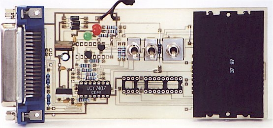
uni5_a.bmp – PCB of parallel programmer UNIPROG V-A
uni5_as1.bmp – schematic diagram of G.Tait’s programmer with 4066
uni5_ao1.bmp – layout of components of G.Tait’s programmer with 4066
 List of components:
1 x slot for ISO card (eight pins are enough)
1 x female Centronix connector 36pin
1 x 74LS06 (7406) or 74LS07 (7407)
1 x 4066
1 x 7805 (78L05)
1 x 7812
1 x 1N4001 D1
2 x 1N4001 (1N4148) D2,D3
1 x LED green
1 x LED red
1 x capacitor 10-47u/25-63V
5 x capacitor 100nF
2 x capacitor 1nF
2 x resistor 100R
2 x resistor 1K0 (1K2)
5 x resistor 10K
2 x resistor 18K
2 x single switch on-on
1 x double switch on-on
1 x socket 8pin
1 x socket 18pin
Programmer by D. Tait with PNP trans.
uni5_a.bmp – PCB of parallel programmer UNIPROG V-A
uni5_as2.bmp – schematic diagram of G.Tait’s programmer with PNP trans.
uni5_ao2.bmp – layout of components of G.Tait’s programmer with PNP trans.
List of components:
1 x slot for ISO card (eight pins are enough)
1 x female Centronix connector 36pin
1 x 74LS06 (7406) or 74LS07 (7407)
1 x 7805 (78L05)
1 x 7812
2 x PNP transistor (BC557)
1 x 1N4001 D1
2 x 1N4001 (1N4148) D2,D3
1 x LED green
1 x LED red
1 x capacitor 10-47u/25-63V
5 x capacitor 100nF
2 x capacitor 1nF
2 x resistor 100R
2 x resistor 1K0 (1K2)
2 x resistor 4K7
7 x resistor 10K
2 x single switch on-on
1 x double switch on-on
1 x socket 8pin
1 x socket 18pin
Programmer by H. Schaer
uni5_a.bmp – PCB of parallel programmer UNIPROG V-A
uni5_as3.bmp – schematic diagram of H.Schaer’s programmer
uni5_ao3.bmp – layout of components of H.Schaer’s programmer
| Type | Chips | SW1 PR1 |
SW2 PR2 |
SW3 PR3 |
| A. 1xPIC (RB7) – single PIC card | SLAVE(RB7) | A | A | A |
| B. 1xPIC (RB6) – single PIC card | MASTER(RB6) | A | A | B |
| C. 1xPIC (RB7), 1xEEPROM – Multimac II | EEPROM SLAVE(RB7) |
B A |
B A |
B A |
| D. 2xPIC (RB6, RB7) – twine PIC card | MASTER(RB6) SLAVE(RB7) |
A A |
A A |
B A |
| E. 2xPIC (RB6, RB7), 1xEEPROM – quadra | EEPROM1 MASTER(RB6) SLAVE(RB7) |
B A A |
B A A |
B B A |
| F. 2xPIC (RB6, RB7), 2xEEPROM – quadra
Attention! EEPROM2 can be programmed only in a socket! |
EEPROM1 MASTER(RB6) SLAVE(RB7) EEPROM2 |
B A A – |
B A A – |
B B A – |
| G. 1xPIC(RB7) – wafer card | PIC | A | A | A |
| H.1xPIC(RB7), 1xEEPROM – MM2 wafer card | EEPROM PIC |
B A |
B A |
B A |
| J. 1xPIC(RB7), 1xEEPROM – gold MM2 wafer card use Phoenix interface for EEPROM |
PIC
EEPROM |
A
– |
A
– |
A
– |
List of components:
1 x slot for ISO card (eight pins are enough)
1 x female Centronix connector 36pin
1 x 74LS06 (7406) or 74LS07 (7407)
1 x 7805 (78L05)
1 x 7812
2 x PNP transistor (BC557)
1 x 1N4001 D1
2 x 1N4001 (1N4148) D2,D3
1 x LED green
1 x LED red
1 x capacitor 10-47u/25-63V
4 x capacitor 100nF
2 x resistor 1K0 (1K2)
10 x resistor 10K
2 x single switch on-on
1 x double switch on-on
1 x socket 8pin
1 x socket 18pin
For more detail: PIC programmers for parallel port
About The Author
Ibrar Ayyub
I am an experienced technical writer holding a Master's degree in computer science from BZU Multan, Pakistan University. With a background spanning various industries, particularly in home automation and engineering, I have honed my skills in crafting clear and concise content. Proficient in leveraging infographics and diagrams, I strive to simplify complex concepts for readers. My strength lies in thorough research and presenting information in a structured and logical format.
Follow Us:LinkedinTwitter