
Abstract
The objective of this project is to produce a PIC evaluation/development board to be used by future ECPE senior design project teams. Many project implementations call for some sort of microcontroller unit in the final product, and this need can often be met by a simple PIC microcontroller. However, the development of a PIC solution is often beyond the expertise and available time of the design team. The board to be produced by this project will enable design teams to quickly and easily develop a PIC for use in their projects. The board will include a wide variety of input and output devices and interfacing ports. It will also be designed to provide a high degree of flexibility, giving future design teams the needed functionality to produce a successful end product.
Acknowledgement
Special thanks is due to our faculty advisors, Dr. Rover and Dr. Weber. They have provided valuable advice and insight, and continue to play an active role in enabling the development of this project to its maximum potential.
1. Introduction
1.1 General Background
Many senior design and other class design projects within the computer and electrical engineering department require a micro controller unit (MCU). However, before they can be used in a design project, these units require additional components and design, often beyond the expertise or time available within a design team. The objective of this project is to design and fabricate an evaluation/development board for a PIC, which will provide the required power supply, frequency source, and other supporting components needed to realize a fully functional, low cost, “off-the-shelf” MCU for use in future senior design projects. Having such units readily available will allow senior design teams to concentrate on completing their assigned design rather than expending time and effort on supplementary components. Full documentation will include tutorials and design guides for using the PICs in various applications.
1.2 Technical Problem
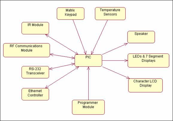
In order to implement a development board for a PIC, there are several components which must be designed to work together. The components used will provide a design team with flexibility of use which will allow the board to be used in varying applications. Necessary apparatus includes the microcontroller unit (MCU), and one or more of the interfacing components. The PIC evaluation/development board will include a LCD display, general purpose output LEDs, LED bar graphs, 7-segment displays, a RS232 port for serial PC interfacing, and a matrix keypad. These devices will allow the board to be quite versatile.
1.3 Operating Environment
Because this product is designed to be used as a “stepping stone” in future senior design projects, an exact operating environment is unknown. However, it is preferable for the board to be capable in as wide of a range of environments as possible to allow the most flexibility. The operational range will be from -20˚C to 80˚C and from 0-90% humidity. By adding further casing around the board it may be possible to further extend the operational range.
1.4 Intended User(s) & Use(s)
The PIC evaluation/development board will be designed for use by people with experience with electrical and computer engineering. More specifically, this board is intended to be used by students in future senior design projects. The very design of this board allows for a variety of uses. These uses could include, but are not limited to: data acquisition, control, or information processing. Other users of this product could include faculty members, as well as undergraduate students in a lab environment.
1.5 Assumptions & Limitations
The following assumptions and limitations impact the implementation of the project.
Assumptions:
Users have an electrical/computer engineering background.
Users have access to a personal computer with a free parallel port.
Limitations:
Budget of one hundred dollars.
Typical PCB fabrication uses 12”x12” boards. Therefore the layout at a maximum must fit that constraint. The goal is to make the entire board smaller than a sheet of paper (8½”x11”).
Environmental factors- The board must be able to operate in a “normal” environment. This consists of no abnormal EMI fields, no water and no extreme temperatures (outside of the operating ranges of the components).
2. Design Requirements
2.1 Design Objectives
Support for multiple PICs – The board will have the capability to accept several selected models of PICs.
Versatile – The PIC evaluation and development board will be useful in a wide variety of applications. The board will be designed in a flexible manner to allow the user to connect the PIC to any of the components on the board.
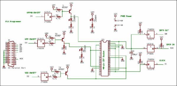
Programmer – The board will include a PIC16 programmer, as well as the software required to develop and upload the program to the PIC.
Multiple output devices – The board will include a character LCD display, general purpose LEDs, an LED bar graph, 7-segment displays, and a speaker.
Input capabilities – The user will be able to give input to the PIC with a matrix keypad, several on-off push buttons, DIP switches and digital and analog temperature sensors.
Interfacing capabilities – The board will have the capability to interface with other devices via an RS-232 serial port and an infrared transceiver, as well as via any interfacing ports built-in to the selected PIC.
2.2 Functional Requirements
Provide solutions for a variety of applications – The user will be able to program (and reprogram) his or her selected PIC using the integrated PIC16 programmer. Once programmed, the PIC can be inserted into a socket similar to a solder-less breadboard, allowing the user to connect and disconnect devices on the board as needed.
Allow development of several PICs – The user will be able to design a system with any of a number of selected models of Flash reprogrammable PICs – 18-, 28-, and 40-pin models. The board will provide the capability to swap PICs quickly and easily.
User-friendly design environment – The board will be packaged with a simple design environment for programming and testing. The design environment will include a number of ASM libraries to support the board’s devices.
Well-documented – The package will include extensive documentation, including tutorials and design guides, so that the user will be able to quickly adapt the board to any application.
2.3 Design Constraints
Cost – Care must be taken to limit the cost of the board components as well as the complexity of the design, both to meet the budget of our own team and to ensure that future design project teams will be able to use the board within the means of their budget
Environment – Because this board is being designed to accommodate unknown future projects, it must be designed to operate in a wide range of environmental conditions. The possible operating range will be defined as -20º – 80ºC and 0 – 90% humidity.
Size – The board must be small enough to be practical for most applications, without sacrificing versatility.
For more detail: PIC Evaluation/Development Board Implementation
About The Author
Ibrar Ayyub
I am an experienced technical writer holding a Master's degree in computer science from BZU Multan, Pakistan University. With a background spanning various industries, particularly in home automation and engineering, I have honed my skills in crafting clear and concise content. Proficient in leveraging infographics and diagrams, I strive to simplify complex concepts for readers. My strength lies in thorough research and presenting information in a structured and logical format.
Follow Us:LinkedinTwitter