PIC development/testing board
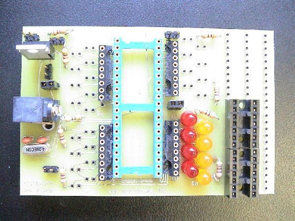
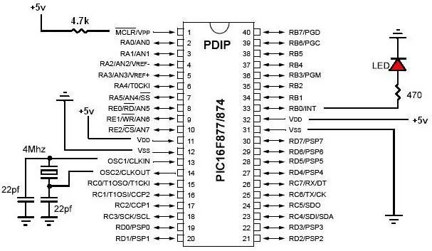
Here’s a PCB design for a bare bones PIC16F877 development board. All you need is a 4mhz crystal, two 22pf caps, one 4.7k resistor, and eight 470 ohm resistors, a 7805 regulator (not necessarily necessary, read below), and some LEDs (you don’t need to put all 33 LEDs on, just as many as you need to debug your programs).

this board is useful for project development because:= it will show you pin states on the LEDs (if the LED jumper is on) in an easy to read way (the board reorganizes the PIC pins so all the pins on the same port are next to each other)

this board is useful for project development because:= it will show you pin states on the LEDs (if the LED jumper is on) in an easy to read way (the board reorganizes the PIC pins so all the pins on the same port are next to each other)
= it allows easy prototyping interface with the PIC via either (A) the top holes of the wire wrap sockets on the sides or (B) the wire wrap posts underneath
= allows easy power connection
= allows slight expansion on the right side (can put a small circuit there for serial interface or whatever)
====================
download ExpressPCB (look it up on the net)
download the .pcb file
open the file, click ‘layout’, click ‘order via internet’ and you can get three of these boards for $59 total (includes shipping) if you click the mini-board option.
enjoy
====================
For more detail: PIC development/testing board using PIC16F877 microcontroller


