Description :
The purpose of this timer is to provide a countdown time from 1 second to 99 minutes & 59 seconds. I use it to control the lighting for the Ultra-Violet exposure of photosensitive PCB material. The project provides also an audible alarm at the end of the countdown time and switches the UV lights by means of a relay. It is based on a Microchip microcontroller, the 18 pin PIC16F84(A). This microcontroller contains 1Kbyte of flash memory for program code, 64bytes of static RAM memory, and 64bytes of EEPROM memory which are used here to store up to 15 different (user-programmable) countdown times.
The Power Supply Unit (PSU) schematic is simple and straight :
The 2x9VAC from a 3VA transformer is rectified by diode D5 & D6 and smoothed by C11 & C12 to obtain about 12VDC voltage.
This 12VDC is then used to feed voltage regulators IC5 & IC6:
– IC5 (7805 regulator) delivers the +5V voltage for the logic (PIC, 4543, relay and buzzer).
– IC6 (7808 regulator) delivers a +8V voltage to feed the four blue Common Anode displays.
If other display colours are used (red, green, yellow) the +8V power supply can be omitted and the displays feeded by the +5V for the logic.
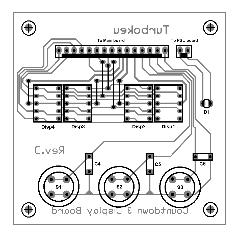
The main schematic :
The main part in the schematic is of course the PIC16F84.
It takes care of the scanning of the pushbuttons, multiplexing the display output and activation of the relay and buzzer while running several timing routines for accurate countdown.
Fifteen countdown times can be stored into EEPROM memory. The timer starts automatically with the countdown time stored in the first EEPROM memory location.
The lower nibble of PORTA is used to drive the 4543 ‘BCD to 7-segment driver/decoder’, the lower nibble of PORTB to drive the 7-segment digits through transistors T1 to T4.
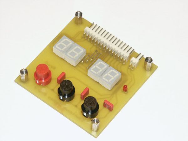
Three push buttons allow for user input:
S1 – START/STOP push button: Starts the actual displayed count down time, or interrupts (stops) the countdown in progress.
S2 – SET push button: Allows to set the desired countdown time by litting every digit in turn (every push lits the following digit: M10,M1,S10,S1).
Waiting between pushes increments the active digit by one every second. After the last digit (second units) has been set the configured countdown time is automatically saved into the active EEPROM memory location.
S3 – SELECT push button: Allows to browse through the 15 EEPROM memory locations to retrieve the desired stored countdown time. Setting a new countdown time through the SET push button stores it automatically into the active memory location.
A 50ms beep from the buzzer confirms every key press.
At the end of the countdown time (00:00) the buzzer sounds intermittently (1Hz, 0.5sec on, 0.5sec off) until the START/STOP button is actionned, and the initial countdown time is displayed again for a next countdown.
Timer0 overflow interrupt is enabled and the prescaler (16) is assigned to Timer0. With an oscillator frequency of 4MHz this gives a Timer0 overflow (and interrupt) every 4.096 msec: 1 / [ ( 4000000 / 4 ) * 16 * 256].
When programming the 16F84(A) set the configuration word to 3FF2h : CP disabled, PWRT enabled, WDT disabled, HS oscillator enabled).
As the 16F84(A) becomes obsolete and more expensive than the 16F6x8 (16F628 with 2KB program memory, and 16F648 with 4KB) which are pin-compatible, I made also a firmware version that works with these (CNTDWN3-628-PNP.ASM), and the corresponding HEX file.
The only differences with the 16F84 firmware are:
– Initialization of PORTA as digital I/O ports (default is A/N ports).
– Relocation of the GPR (General Purpose Registers) variables from OCh to 20h.
– Modification of Indirect Addressing Pointers to point to the new GPR addresses.
– Modification of the bank selections when accessing the EEPROM memory.
When using a 16F6x8 instead of a 16F84, the 4MHz crystal (XTAL1), the 22pF capacitors (C1 & C2) and the connection of the MCLR pin to +5V can be omitted as the 16F6x8 microcontrollers series include an internal calibrated 4MHz RC-oscillator which is set by configuring the correct bits of the configuration word during programming (2149h : CPD disabled, CP disabled, LVP disabled, BOR enabled, MCLR internally, PWRT enabled, WDT disabled, Internal oscillator enabled).
For more details visit: PIC Countdown Timer using PIC16f84a
About The Author
Ibrar Ayyub
I am an experienced technical writer holding a Master's degree in computer science from BZU Multan, Pakistan University. With a background spanning various industries, particularly in home automation and engineering, I have honed my skills in crafting clear and concise content. Proficient in leveraging infographics and diagrams, I strive to simplify complex concepts for readers. My strength lies in thorough research and presenting information in a structured and logical format.
Follow Us:LinkedinTwitter