
One of my circuits that I build quite often (20 – 40 at a time), uses a PIC 12F675. I had the following issues:

- The boards that I make, does not have in-circuit programming capabilities. This is to allow for a small PC board layout. PICs thus need to be programmed out of circuit.
- I only have a PICkit 3 programmer, which does not have a convenient ZIF socket to program a stand-alone PIC. To program a PIC, I have to set up a circuit on breadboard.
- To test the programmed PIC, and set certain parameters, the circuit still needs to be on a breadboard.
- To test the circuit, external equipment is needed (Servo tester, 5V BEC, 3 cell LiPo battery, and the load driven by the circuit.
- Sometimes, the PICkit 3 erases the calibration bit on the PIC. This prevent my circuit from working. To reprogram the calibration bit, another circuit is needed to determine the correct calibration bit.
This board started as a tool to speed up the calibration bit programming on the PIC 12F675 without the need for additional components or wires.
Soon, I realised that the same circuit can also be used to upload hex files to a PIC.
Finally, with a screen and 2 buttons, I added a test routine to the same circuit, so that I can adjust the parameters, and perform an operational test of the final software on the PIC.
The final board now performs the following functions::
- Programming of a PIC using a PICkit
- Calculating and programming of the calibration bit of the PIC
- Testing of a PIC final software and parameters.
Step 1: The Circuit
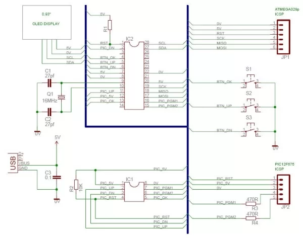
An ATMEGA328p is used as interface to the PIC 12F675,
Power to the PIC is controlled by the ATMEGA.
All pins of the PIC, apart from the reset pin, can be controlled via the ATMEGA.
The PICkit header pins allow for easy connection of the PICkit programmer to the circuit, and allows for a quick way to read/program the PIC.
The on-board screen is used for selection and display of steps and statuses.
Three buttons allow for menu navigation and parameter setup.
The ATMEGA can be programmed in circuit via the 6 pin ICSP headers.
Step 2: The PC Board
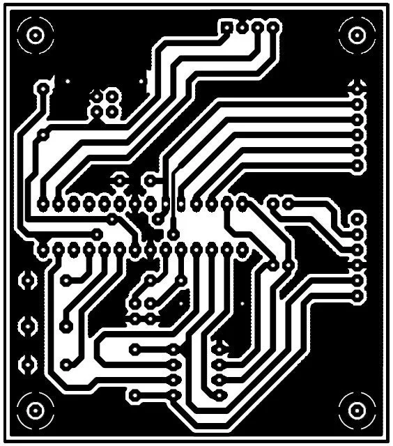
All components required, are mounted onto the PC Board.
Because the PICkit can not deliver enough power to drive the ATMEGA328p and LCD display, power for the circuit is obtained via a USB cable.
Assembly of the board is simple, and uses only through-hole components.
Once the PC Board is assembled, you can program the ATMEGA328p via the on-board ISCP headers.
All files required for the project, are attached.
Attachments
Step 3: Using the Board
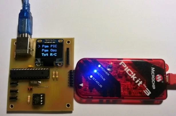
To use the board, follw these steps:
- To power the board, connect a standard USB cable between the board and computer.
- Connect the PICkit programmer to the headers, and to the computer.
- Open MPLab.
- Select PICkit as programmer.
- Select PIC 12F675 is device.
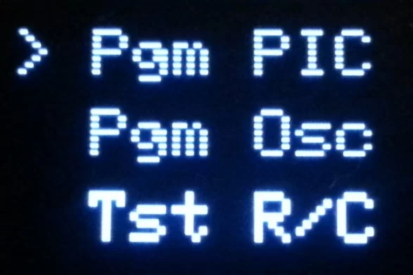
- From the menu on the screen, select the required option.
- Follow the on-screen instructions.
Step 4: Programming a PIC 12F675
Follow the step:
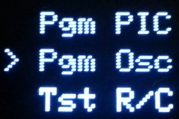
- From the menu, select “Pgm PIC”
- The menu selection will be displayed briefly on the screen.
- You will be asked to insert a PIC. Press Ok after PIC is inserted.
- The next screen will prompt you to program the PIC.
- During this step, power to the PIC is turned on.
- In MPLab, load your file/project.
- Select programmer as PICkit.
- Upload program to chip.
- When done, press Ok.
- Power to the PIC is turned off at this stage.
- You will be asked to insert a PIC.
- It is now save to remove the PIC. Repeat for next PIC if required.
To exit the programming mode, press Up or Down button when asked to insert 12F675.
Step 5: Determine the Calibration Bit
Follow the step:
- From the menu, select “Pgm Osc”
- The menu selection will be displayed briefly on the screen.
- You will be asked to insert a PIC. Press Ok after PIC is inserted.
- Program the PIC with “OscCal.hex” This file needs to be loaded onto the PIC to determine the value of OSCAL.
- During this step, power to the PIC is turned on. In MPLab, import the file “OscCal.hex”.
- Select programmer as PICkit.
- Upload program to chip.
- When done, press Ok.
- Power to the PIC is still on at this stage.
- A 1000Hz test signal will be generated by the PIC. During this step, the PIC will be controlled by the ATMEGA to determine the OSCAL value closest to 1000Hz.
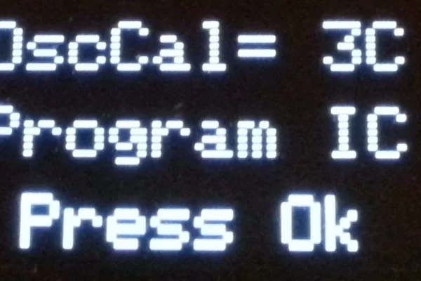
- When done, the correct value of OSCAL will be displayed.
- Program this new OSCCAL value into the calibration bit of the PIC.
- When done, press Ok.
- Power to the PIC is turned off at this stage.
- You will be asked to insert a PIC.
- It is now save to remove the PIC. Repeat for next PIC if required.
- If the correct file (OscCal.hex) is not loaded, PIC not Found message will be displayed.
To exit the calibration mode, press Up or Down button when asked to insert 12F675.
Attachments
Step 6: Programming New Calibration Bit in MPLab
When the screen displays the newly found OscCal value, do the following:
- In MPLab, open the EEPROM view.
- Read the PIC.
- The last two lines will contain the the OSCAL details.
- Memory location 0x6F will contain the OSCAL value stored on the PIC if it was not erased. There is no need to program the new calibration bit. Press Ok to continue.
- Memory location 0x7F will contain the calculated new OSCAL value. This is the value of the calibration bit that needs to be set in MPLab.
- Open the Setting window, and select Calibration Memory.
- Select “Allow PICkit to program calibration memory”.
- Enter the new calibration value as displayed on the screen. Apply changes.
- Next, program the file “OscCal.hex” file again to the PIC.
- MPLab will warn that it is about to program new calibration data to the PIC. Select YES.
- Your PIC calibration data has now been restored.
- When done, press Ok.
- Power to the PIC is turned off at this stage.
- You will be asked to insert a PIC.
- It is now save to remove the PIC.
- Repeat for next PIC if required.
To exit the calibration mode, press Up or Down button when asked to insert 12F675.
Step 7: Testing of PIC 12F675 – Specific Circuit
NOTE:
This part is a demo of what the Test menu does. This testing is done for a specific function, and the user can change the test sequence by editing the ATMEGA328p file.
This part of the board test a programmed PIC for correct parameters. The “PicTest.hex” must be loaded into the PIC for this to work.
The ATMEGA is used to simulate a signal on one of the PIC pins. It then test the correct operation by comparing the input signal to outputs on a PIC pin.
Follow the step:
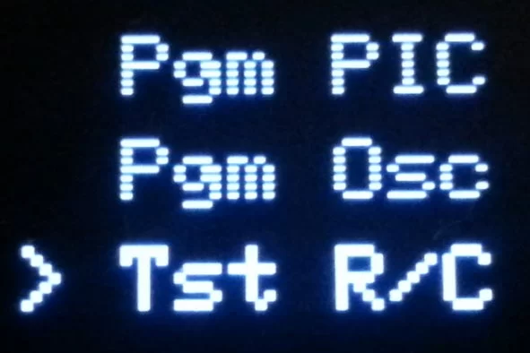
- From the menu, select “Test R/C”
- The menu selection will be displayed briefly on the screen.
- You will be asked to insert a PIC.
- Press Ok after PIC is inserted.
- During this step, power to the PIC is turned on.
- The next screen will display the test status.
- When the test is done, and program works correct, PIC Passed will be displayed briefly on the screen, followed by the test results.
- When the test fail, PIC Failed and a corresponding error code will be displayed.
- When done, press Ok.
- Power to the PIC is turned off at this stage.
- You will be asked to insert a PIC.
- It is now save to remove the PIC.
- Repeat for next PIC if required.
To exit the test mode, press Up or Down button when asked to insert 12F675.
Attachments
Source: PIC 12F675 Programmer/OscCal Restore/Tester
About The Author
Muhammad Bilal
I am a highly skilled and motivated individual with a Master's degree in Computer Science. I have extensive experience in technical writing and a deep understanding of SEO practices.