
Abstract
Parallel parking is often the most difficult part of ordinary drivers, and one of the most feared tasks for some. Big cities specifically require great amount of parking skills as parking spaces are often limited. Removing the difficulty, stress and uncertainty of this task is very appealing. That is why renowned automobile companies like Tesla, Ford and BMW have implemented this technology. Imagine finding the parking spot of your choice and by simply pressing a button your car autonomously parks itself. As this technology becomes more popular, the consumer demand elevates in proportion. Hence we have built a low-cost prototype which would enable a car to find a suitable parking space and park itself without any assistance from the driver.
Already existing systems are expensive and can cost anywhere between $700 (2003 Toyota Prius) and $3000 (IRVW Futura) in addition to the car’s cost. They employ expensive lasers and cameras to sense obstacles and calculate the parking area.
In this project we have developed a low cost system with a budget of $71.90 and uses Ultrasound Sensors on a PIC32 architecture to map the distance and obstacles. Our system is able to calculate the length of the parking space and determine if the car could be parked in that particular spot or not. If it could be parked, the car successfully parks itself into the parking space.
High Level Design
Hardware
Our system is mainly composed of five ultrasonic sensors (HC-SR04, a dual motor driver, a PIC32MX250F128B microcontroller, a TFT display and two DC motors with gear boxes. The car is capable of parking autonomously after it detects a parking space on its right side. There is one sonar on the front, one on the back, two on the right side and one on the back right corner of the vehicle. One of the side sensors is in charge of keeping the car aligned to the parking space boundaries using a closed-loop Proportional-Integral (PI) controller.
DC motors are controlled using PWM signals from the MCU, and through the motor driver (TB6612FNG), which is capable of simultanously driving the two motors at up to 1.2A of constant current (3.2A peak current). The driver consists of a dual H-bridge with stop and break capabilities, as explained in the Hardware section.
A TFT display provides a very useful user-interface as it provides information to the user of the current parking state of the vehicle as well as all sensor readings. The display was a fundamental piece in the optimization and debugging of the system.
Software
Our system consists of two Finite State Machines (FSM); one for detecting the parking spot, and the other for accurately performing the parking algorithm. The FSMs work at different times, that is, the parking algorithm is executed only when a parking space has been detected, after which the first FSM is no longer scheduled to be executed.
Miscellaneous
The chassis used for the project was obtained from an RC car that we purchased online. The PCB and attached wires were removed from the car in order to incorporate our design. The wheels, DC motors, and gear boxes were also used for the project. The DC motors have a continous current rating of about 0.75A, with peak and stall currents of 2A and 2.69A, respectively. The board built and two battery packs were fit into the available space on the car.
Hardware
Stand-Alone PIC32
The first task of the project was to develop a completely stand-alone system that would allow us to run the MCU with a power supply (battery pack) without the need of using the development board (Microstick II) provided in lab. The stand-alone system was very straight forward to make; only capacitors, resistors, a pushbutton, and a PIC32MX250F128B microntroller were used. The schematics of our design is shown in Figure 1 below.

As it can be seen in Figure 1 above, decoupling capacitors on power supply pins such as Vdd, Vss, AVdd, and AVss were used. It is recommended in the device datasheet that values of 100nF and ceramic capacitors be used. Also, the capacitors should be a low Equivalent Series Resistance (lowESR) and have resonance frequency in the range of 20 MHz and higher. Also, the datasheet recommends that the VCAP pin must not be connected to VDD, and must have a CEFC capacitor, with at least a 6V rating, connected to ground. For this, we used a 10μF polarized capacitor connected between VCAP and GND (pins 20 and 19 on the MCU).
In addition, we implemented a pushbutton for the Master Clear (MCLR) pin. This is an active low pin and provides for two specific device functions: device reset and device programming and debugging. For this we used a normally-open switch, which when closed, generates a device Reset. As recommended in the device datasheet, a 10kΩ pull-up resistor was used to limit the current flowing into the pin when the button is pushed.
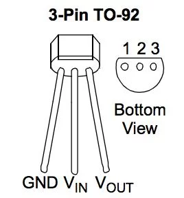
Voltage Regulator
To power the stand-alone system it was necessary to provide 3.3V to the voltage bus, Vdd and AVdd pins. Since a 5V battery pack is used in the system, we had to regulate down the voltage to 3.3V. To do this, we used an MCP1702 voltage regulator, which is a family of CMOS low dropout (LDO) voltage regulators. This regulator has an input operating voltage range of 2.7V to 13.2V. The standard output voltage options are: 1.2V, 1.5V, 1.8V, 2.5V, 2.8V, 3.0V, 3.3V, 4.0V, and 5.0V. With a 5V battery we were able to easily to get a 3.3V rail using this voltage regulator. The schematic is shown in Figure 2 below.
Motor Driver
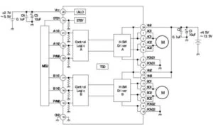
The TB6612FNG motor driver can control up to two DC motors at a constant current of 1.2A per channel. It has a peak current rating of 3.2A. Two input signals (AIN1 and AIN2) are used to control one DC motor in one of four function modes: clockwise, counterclockwise, short-brake, and stop. The other two input signals (BIN1 and BIN2) can be used to control a second motor. Motor outputs for A01 and A02 for one motor and B01 and B02 for a second motor. The two motor outputs (A and B) can be separately controlled. The speed of each motor is controlled via a PWM input signal with a frequency up to 100kHz. An standby pin (STBY) is pulled HIGH to take the motor out of standby mode. The logic supply voltage (Vcc) can be in the range of 2.7-5.5VDC. For this project, the Vcc line is supplied through a 3.3V voltage regulator (MCP1702-3302) that regulates down the 5V from a battery pack. The motor supply voltage is provided by a separate 5V battery. The motor driver breakout board was purchased on SparkFun, which comes with all components installed as shown below. Decoupling capacitors are included on both supply lines to reduce surrounding noise from the motors. With this motor driver it was not necessary to use opto-couplers to drive the motors, due to its very good motor noise cancellation. In fact, we ran the motors with and without opto-couplers and the results were identical.
The motor driver consists of a dual H-bridge as shown below. In order to driver a motor, one input (IN1 or IN2) needs to be driven HIGH while the other input pin is driven LOW. This would cause the motor to rotate in one direction. To reverse the direction of the motor, the state of the pins needs to be inverted. The H-bridge is constructed of two P-channel MOSFETs connected to the high voltage bus (Vm), and two N-channel MOSFETs connected to the low voltage bus (GND). In order to drive the motor, one of the P-channel MOSFETs and the N-channel MOSFET on the opposite side need to be set HIGH, while the other two MOSFETs (N and P-channels) need to be set LOW. To reverse the direction of the motor, we simply have to reverse the operation. It is important to note that a P and N-channel MOSFET from the same branch should never close (set HIGH) at the same time. This creates a low-resistance path between power and GND, effectively short-circuiting the power supply, and potentially destroying the circuit.
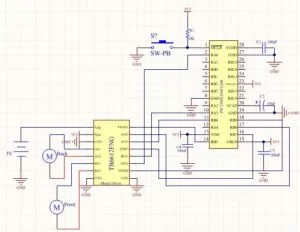
As shown in the figures above, in order to rotate the motor in the clockwise direction, IN1 needs to be set HIGH, while IN2 needs t be set LOW. Setting these pins in the opposite way causes the motor to rotate in the reverse direction, that is, counterclockwise. It is important to note that the STBY pin needs to be set HIGH at all times in order for the motor to be able to spin. Shown below is the schematics of the motor driver showing how we hooked up the stand-alone PIC32 MCU and the driver. As it can be seen, pins RB8 and RB4 of the PIC are configured as the input pins (output pins of the MCU) AIN1 and AIN2 in order to drive the back motor of the car, whereas pins RA3 and RA0 represent BIN1 and BIN2 and drive the front motor for steering. The STBY pin is configured as RB7 on the PIC.
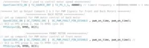
In addition, the speed of the motors are controlled via a PWM input signal with a frequency that can go up to 100kHz. For our application, we decided to set the PWM input signal at 1kHz via two output compare units OC2 and OC3. The output compares medidate the PWM signal, and run off of Timer 2, which is set at a frequency of 1kHz. Time 2 feeds into both output compare modules, which then feeds into two equality operators (OCXR) and OCXRS. Every time the timer ticks, the two equalities take place and a square wave is generated, thus setting the period of the PWM signal. Output compare OC2 is used for controlling the speed of the back motor (motion speed), whereas OC3 is used for controlling the front motor speed, which is used for steering the vehicle. As shown in the schematics above, the pins RB5 and RB9 are set as OC2 and OC3, respectively.The software setup of the output compare units is shown below in Figure 3.
Ultrasonic Sensors
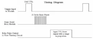
As mentioned above, five ultrasonic sensors were used in our autonomous system. Two sensors were place on the right side of the car, one on the front, one on the back and another one on the right back corner of the vehicle. The ultrasonic ranging module is the HC-SR04, which provides 2-400cm non-contact measurement function, with a ranging resolution of 3mm. Each module, which we purchased from RobotShop, includes an ultrasonic transmitter, receiver and control circuit. The operation of the sonar is initiated by supplying a short pulse of at least 10 μsec to the trigger input. Then the module sends out an 8-cycle burst at 40kHz, after which an echo pulse is raised. The echo pulse is then reset after the ultrasound has bounced off of the object and reached the receiver side of the module. Thus, the echo pulse is proportional to the distance between the sensor and the object; the pulse increases as the distance gets larger. Calculating the time the echo pulse remains HIGH provides information about the distance of the object from the sensor. Figure 4 below shows the timing diagram of the sonar module.
Calculating Distances with Sonars
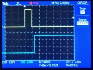
By measuring the time the echo signal remains HIGH we can calculate how far the object/obstacle is from the sensor. Since the speed of sound is 340 m/s, the distance is obtained by: d=t_H*v_sound/2 =t_H*(340m/s)/2. It is recommended by the manufacturer to wait at least 60 msec between triggering events in order to prevent signal interference. Shown below in Figure 5 are the waveforms for the trigger and echo signals of an object located very far (left image) and 10 cm (right image) from the sensor.
Interrupt Service Routine for Echo detection
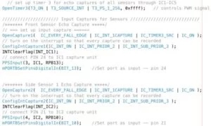
As mentioned earlier and depicted in Figure 5 above, after the trigger pulse is set and the internal 8-cycle burst is emitted, an echo pulse is set HIGH. The pulse then resets after the signal bounces off of the obstacle and reaches the receiver side of the sonar. In order to compute the distance of the object from the sonar, it is important that we accurately measure the length of the echo pulses for each sonar. To do this, we implemented five timer capture Interrupt Service Routines (ISR), one for each sensor, that are in charge of capturing the falling edge of the echo pulses. We selected input capture 1 through 5. The five ISRs run off of Timer 3, which clocks at a frequency of 2.38Hz (0.42 seconds). Since it is necessary to wait at least 60msec between triggering events and 1msec for the triggering pulse, we did not have to run the ISRs at a very high frequency. In fact, 2.38 Hz worked fine for our application, considering that the speed of the car is quite slow. Figure 6 below shows how we set up timer 3 as well as the setup for the five ISRs. As it can be seen in the image on the left, Timer 3 is a free-running timer with selected prescaler of 256. The input capture ISRs are configured to triggger every falling edge of the echo pulse and are set with a interrupt priority of 2. Since we need the same type of information at the same time from all ISRs, it was not necessary to have different priority levels for the interrupts. The image on the left shows how the interrupts for input captures 1 and 2 were set up (we have omitted the other 3 ISR setups in the figure to save space). Notice that the capture pins are set as input pins. Pins RB13, RB10, RB11, RB15, and RA2 were selected for the input capture interrupts 1 through 5 for the front, side 1, side 2, corner and back sensor, respectively. The image on the right of Figure 6 shows how to set up the function calls and read the captured events from the ISRs. The captured events are stored in the curr_capture(1-5) variables, which are later used in the code to compute the respective distances detected by the each sonar. It is critical that we clear the interrupt flag right after the ISR has triggered; failure to do so may cause that the ISR will never triggered again.
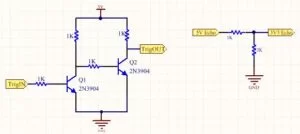
Voltage Level Shifters
The HC-SR04 sonar modules have 4 pins: Vcc, GND, Trigger and Echo. The operating voltage is 5V, which is supplied by a battery pack. The working current is 15 mA. Since the trigger needs to be a 5V pulse and the PIC32 MCU can only supply 3.3V, a level shifter was designed in order to raise the voltage to 5V. Each level shifter is composed of two NPN transistors (2N3904) and 1kΩ resistors, as shown in Figure 7 below. In order to be able to use five sonars, given the limited amount of available pins on the MCU, it was necessary two drive three sensors with the same trigger. The two sonars on the side, and the one on the corner were driven with a trigger on pin RA4. The signal from this pin is passed through a level shifter, which then feeds the three sensors a 5V triggering pulse. Another trigger was employed to drive the sonars on the front and back. For this, pin RB3 was set as the trigger, whose output (3.3V output) is raised to 5V through the level shifter, which then feeds the triggering pulse on the sonars. Figure 7 shows the schematics for this part. Therefore, only two level shifters were used, as oppose to five, which we could not have afforded given the limitations on the number of available pins. This, on the other hand, raised questions about possible interference between sensors and capability of a single pin to provide a working current to the sonars. However, after some testing we were able to see that triggering three sensors with the same trigger does not introduce inaccurate measurements.
Voltage Dividers
It was necessary to build five voltage dividers to reduce the 5V echo pulses from each sonar to 3.3V, which need to be captured by the MCU input capture modules. For this we selected 1kΩ and 2kΩ resistors, as shown in Figure 7 below. Although there are some pins on the PIC that are 5V tolerant, we decided not to use the 5V capabilities as there are not five 5V tolerant pins. Thus, we kept the design for all sensors the same.
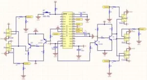
Shown below in Figure 8 is the schematics for our design, including the stand-alone PIC32 microcontroller, sensors, level shifters and voltage regulators. As it can be seen, two level shifters and five voltage dividers were designed and implemented.
TFT Display
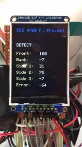
The TFT display was fundamental in debugging our system. In particular, it provided us with direct information about the sensors, such as measured distance and accurary in the readings. The TFT also helped tremendously in developing the parking algorithm as it provided us with very useful information about every step in the algorithm. The TFT was programmed so that it provides the user with the current status of the vehicle by displaying information such as motion of the car, sensor readings, error measurements, and detection of parking space. Figure 11 illustrates the messages displayed on the TFT at different instances. Figure 12 includes the schematics for connecting the TFT and PIC32 microcontroller.
System Design & Schematic
Shown in Figure 12 is the complete schematic of our system. The schematic include a 3.3V voltage regulator and connections for the TFT display, along with all the motor driver and sensors connections with the stand-alone MCU. It is important to reiterate that two 5V battery packs are used in the system. One battery pack powers the PIC32 and TFT display through the voltage regulator (MCP1702) and also provides a 5V line for the ultrasonic sensors. The second battery pack powers the two motors through the motor driver. Headers were used to make the connections between components.
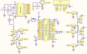
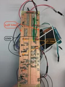
Figure 13 below shows our circuit board with all the components soldered (left image) and wiring connections between components (right image). Notice that there is a 3.3V rail that powers the MCU and a 5V line that supplies power to the sensors and level shifters. An entire line was selected for the ground rail. It is important to mention that a common ground connection was made for all the circuit elements; that is, the batteries, MCU, sensors and motor drivers share the same ground connection.
Software
Software Development
The software for our system consists of two major algortihms: a. Parking Spot Detection Algorithm and b. Parallel Parking Algorithm. Both algorithms were implemented using Finite State Machines (FSM) in order to obtain stability and control over the vehicle. The developed algorithms work as follows:
1. Parking Spot Detection Algorithm
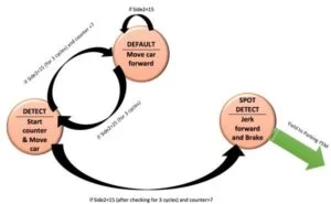
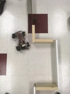
I. DEFAULT: This is the state which the car is immediately in when it is turned on. The car will start at a distance of 8cm from the boundary of the parking space as shown in Figure 14.1 (left image). The system will remain in this state for as long as Side 2 sensor detects a distance of 15cm of less, indicating that a parking space has not yet been detected. During this state, the car will keep going forward at a relatively constant distance from the boundaries of the parking spot as determined by the Proportional-Integral controller. Once the distance detected by Side 2 sonar is greater than 15cm, the system enters in a checking mode, that is, the system checks for the next three consecutive readings to determine the next step. If the next three readings are all greater than 15cm, the system enters in a new state called DETECT. This indicates that the car has reached the start of a possible parking space (see Figure 14.1 below — middle image). If one of the readings is not greater than 15cm, the system will remain in the current state DEFAULT.
II. DETECT: In this state the car has detected a possible parking space. A counter responsible for determining the length of the parking spot is set, and will increment every second until Side 2 sensor encounters a boundary of 15cm or less within the car for three consecutive readings. This indicates that the car has reached the end of a possible parking space. Then the algorithm checks whether the next three readings from Side 2 sensor; if all three are less than or equal to 15cm, the counter stops and the system compares the value of the counter with a pre-determined value, which corresponds to the minimum length of the parking space that the car is able to successfully park in. On the other hand, if the counter value is less than the specified value, which was experimentally selected to be 7 counts, the counter resets and the system enters the DEFAULT state, as the vehicle will not be able to successfully park given the length of the parking space; the car will continue to move forward and execute the same instructions as explained above. In addition, if at least one of the three checks is not less than or equal to 15cm, the algorithm will continue in the DETECT state until it detects another reading less than 15cm, for which it will check again for three times.
III. SPOT DETECT: In this mode the car moves forward and positions itself to correctly reverse back into the parking space (see Figure 14.1– right image). Once the SPOT DETECT state is entered, the algorithm raises a flag that yields control of the car to the Parking Algorithm FSM. Simultaneoulsy, the Parking Spot Detection Algorithm is exited and no longer scheduled.
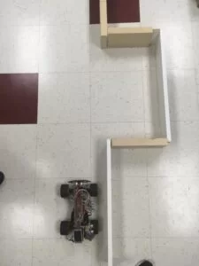
Shown below in Figure 14 is the diagram for this FSM. Figure 14.1 illustrates the actual navigation of the car and the different states it goes through to complete the parking spot detection algorithm.
1. Parking Spot Detection Algorithm
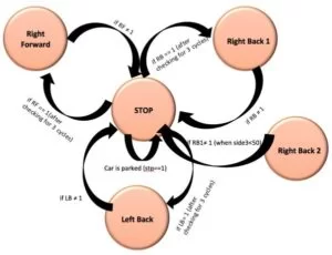
I. STOP: This sate is the default state of the FSM, that is, all states go to the STOP state before ending up in one of the other four states. The STOP state is in charge of checking all the flags set according to sensor readings. It is important to note that a protothread named Flags is in charge of taking all readings from the five sonars and setting flags according to such measurements. The different flags are set by meeting one of the defined criteria. Such criteria have been set through if statements based on sensor readings depending on their position in the parking space. Ranges of sensor values were first estimated by hand based on calculations, and then corraborated experimentally. If a condition in the Flags protothread is met, the respective flags are set and the state is defined as STOP. Then, in another protothread named MotorControl the flags are again checked and the algorithm changes state or remains in the current state accordingly. This procedure continues until the car is parked according to the defined conditions.
II. RIGHT_BACK1: This is the first non-default state that the system enters in after the parking algorithm has been called. The car turns the front wheels to the right and reverses into the parking space. As mentioned above, the STOP state is entered in between states even when the system does not change states. This is done in order to eliminate unwanted behaviors that may be caused by random/erroneous readings. The RIGHT_BACK1 state will continue to be executed for as long as the car is within the limits set by the corresponding condition defined in the Flags protothread.The purpose of the RIGHT_BACK1 state is for the car to be able to separate from the boundary into the parking space. The state will be executed until the the difference between sensors Side1 and Side2 is grater than 15cm, after which the RIGHT_BACK2 state is called, which mainly relies on the corner sensor. Splitting the RIGHT_BACK state into two states (RIGHT_BACK1 and RIGHT_BACK2) provided a smooth transition between RIGHT_BACK and LEFT_BACK. Our initial algorithm only relied on a single RIGHT_BACK state and used only the back sensor to determine the transition from this state to LEFT_BACK; this introduced unwanted behaviors due to scattering of the signal on the back corner of the parking space. Implementing two RIGHT_BACK states (RIGHT_BACK1 and RIGHT_BACK2) completely eliminated unwanted behaviors.
III. RIGHT_BACK2: This state relies on the corner sensor to do the second right and back maneuver. The reason for this is that the corner sensor will be exactly facing the side wall of the parking space by the time this state is called; this way the readings taken from the corner sensor are very accurate and the maneuver is executed with high precision. The condition for the RIGHT_BACK2 state is that the corner sensor is at a distance of at least 25cm from the inner side wall and that the front sensor detects a distance greater than 50cm. The car will continue to reverse with the front wheels turned to the right as long as the corner sensor reading is greater than 25cm. When this condition is no longer met, the algorithm enters in the LEFT_BACK state.
IV. LEFT_BACK: This state is entered as soon as the corner sensor reading is at least 25cm, after which the front wheels turn in the opposite direction (left) and the car continues to reverse until the reading from the corner sensor is 8cm or less, and the back sensor reading is greater or equal to 20cm. These values were obtained experimentally, and provide enough clearance for the car to avoid hitting any of the walls. After the condition is no longer met, the algorithm then transitions to the RIGHT_FORWARD state right after it exits the STOP state. It is important to keep in mind that after exiting a state the system enters the STOP state before transitioning to anew state, as stated before. In this state a three-reading checking was implemented in order to avoid undesired behaviors due to random sensor values.
V. RIGHT_FORWARD: In this state the car steers to the right while moving forward. The condition for this state to occur is that Side3 sensor is less than 15cm, Back is less than 20cm and front sensor is at least 8cm. With this, the car will stop moving right and forward when the front distance is less than 8cm.
After the RIGHT_FORWARD state has been executed, the algorithm checks for how parallel the car has parked; this is done by checking the sensor readings from Side1 and Side2. If the difference between the two sonars is smaller than 3cm and front and back sensor reading are within defined values, the car is well-parked and the algorithm stops its execution, indicating the end of the parking procedure. In the case where the difference between Side1 and Side2 readings is greater than 3cm, the algorithm enters in a correction mode by turning LEFT_BACK. If the “done” condition is met, that is, the car has parallel-parked, the algorithm stops; otherwise, the car goes RIGHT_FORWARD. This correction is done until the car is perfectly parked within the parking space limits.
Shown below in Figure 15 is the diagram for this FSM.
Proportional-Integral (PI) Controller
As explained earlier a PI controller was implemented to suppress the crude steering of the car. It was crucial for our purpose to avoid deviations of the car from the outside parking space boundary. A PI provided some correction and allowed the car to perform a better job while parallel parking. In a PI controller, the proportional and integral terms are computed with respect to an error signal, which is the deviation of the actual sensor reading value from a specified reference distance. We used Side1 sensor for the PI algorithm; that is, the readings taken by Side1 are corrected by the PI controller. The output of a PI controller in the time-domain is as follows:
The Kp and Ki terms in the expression above are the proportional and integral parameters and e(t) is the error term. This error signal is sent to the PI controller, and the controller computes both the derivative and the integral of this error signal. The control signal (u) is then set in the form of PWM through output compare module 3 (OC3), and is equal to the proportional gain (Kp) times the magnitude of the error plus the integral gain (Ki) times the integral of the error. The control signal (u) is sent to the front motor to control the steering of the wheels, and a new output (y) is obtained. The new output (y) is then fed back and compared to the reference to find the new error signal (e). The controller takes this new error signal and computes its derivative and its integral again. The process continues with the goal of keeping the error as close to zero as possible. Since the maximum timer period (Timer 3) is 40000 counts, the proportional term needs to be big enough so as to provide a PWM signal that is within a range that can make the front motor spin. Therefore, we set the proportional term to 2000. Also, the integral term was set to 1, which worked pretty well for our application.
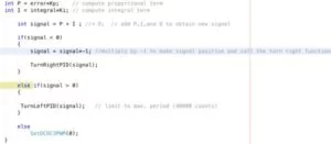
In PID thread there is a conditional statement based on the signal obtained by adding the P and I terms (after being multiplied by the error); that is, the output PWM signal (the one feeding the front motor) is conditional. If the signal C(t) is greater than the timer period, which in our case is 40000 counts, then the output signal needs to be saturated to 40000; thus the signal has to be equal to the timer period. If the signal is greater than zero and smaller than the timer period, the signal is fed in such a way that it makes the front motor to steer to the left. However, if the signal is less than zero and within the count limits, the front motor is fed with the corresponding signal to make the wheels turn in the opposite direction (steer to right). Figure 16 below shows how we implemented this in code.
Protothreads
Sensor thread: computes sensor readings based on input captured events
LCD thread: updates the TFT display with new sensor readings
ParkSpot thread: performs the parking spot detection algorithm (3-state FSM)
PID thread: executes PI controller for controlling steering wheels (front motor) using Side1 sensor values
Flags thread: sets up flags to be used in the parking algorithm based on sensor readings
MotorControl thread: performs the parking algorithm (5-state FSM)
Six protothreads were developed for our system and were scheduled using Round-Robin scheduling. A sensor thread computes the distance of each sensor based on the input capture events. This protothread is scheduled at all times using Round-Robin scheduling, as we need the sensor values at all times. Similarly, an lcd thread is continuously scheduled, and is in charge of updating the TFT screen with new sensor readings and current status of the parking algorithm. Two other threads, ParkSpot and pid are only scheduled while the parking spot detection FSM is active. The ParkSpot thread contains the three-state FSM that is in charge of selecting a suitable parking space. The pid thread contains the PI controller, which controls the steering wheels while the car navigates outside the parking spot. Once a parking space has been successfully selected, a flag is raised and the two threads are no longer scheduled. Immediately after this the Flags and MotorControl threads are scheduled through Round-Robin. The Flags thread is in charge of raising the corresponding flags depending on sensor readings; then the MotorControl thread performs the parking functions through the five-state FSM. It is important to note that once the parking process has finalized and the car comes to a complete stop a done flag is raised signaling the termination of the parking algorithm. This causes the two threads to stop being executed, thus avoiding any possibility of a random sensor reading to disturb the system from its culmination. The sensor and lcd thread continue to be executed even after the done flag has been raised; we want to have sensor readings updates on the TFT at all times.
Results
Accuracy
Our final product is capable of accurately detecting a parking spot that is suitable for the car to park. Parking spaces are detected with 100% precision, given our extensive optimization to the system. In addition, the car is able to correctly maneuver into the parking space as determined by the parking algorithm that was implemented. The algorithm includes corrections in case the car is not exactly parallel to the outside boundary at the moment it starts parking. Corrections are also made if the car is not relatively parallel to the inner wall. However, the accuracy, that is, how well/parallel the car ends up in the parking space depends on the position it starts its maneuver right after it detects an appropriate parking space. Our PI controller was designed to correct any possible deviation of the car from the outside wall. However, due to the crude steering of the front motor, the PI controller is sometimes not enough to exactly align the car with the wall at the desired distance. This sometimes causes that the car would not park completely parallel to the inner wall. However, the car is able to get into the space very accurately without hitting any walls. Starting the parking execution at the correct distance from the wall (about 8cm) produces an excellent maneuvering that contributes to a perfectly parallel result, which occurs 100% of the time.
Issues Faced and Future Work
As mentioned earlier, one of the major issues we faced was our lack of control on the DC motors. Because of their high RPM- low torque property, it was hard to limit the back motor speed so as to allow the PIC to have ample time to log the sensor values and at the same time keep it high enough for the car to actually move. Providing a low PWM signal to the back motor so as to produce a low speed for the car did not provide enough torque to overcome the initial inertia of the system. At the same time, providing a high speed caused the car to go way faster than we needed it to. Thus we had to rely on periodic high PWM bursts and short brakes to control the movement of the car. This provided a solution to this issue, which worked very well for our application.
The next major issue we faced was because of the mechanical defect that the car came with. It turns out that the front wheels were not perfectly aligned with each other. Thus the car never moved in a straight line and tended to veer towards the left. This was undesirable as the starting position of the car is an important parameter in ensuring that the car parks perfectly. Hence we had to implement a PI (Proportional Integral) control to ensure that the car keeps a constant distance with the wall while it is detecting the parking spot. However, due to the bang-bang behavior of the steering wheels (front motor) it was difficult to control such steering, even with the PI controller. This is because the wheels wouldn’t turn at varying degrees; instead, it had to be steered completely in one direction or the other. However, we did implement a PI controller which helped in resisting the natural orientation of the wheels and kept the car at a constant distance from the wall before it starts the parking algorithm. One thing the user must ensure is that the parking spot detection algorithm must be started when the car is at particular distance from the wall (8cm in our case, must be scaled according to the size of the vehicle), the PI would take care of the rest. Too much deviation of the car from the wall directly affects its maneuvering into the parking lot. Although the PI controller significantly helped keeping the car in straight line during its navigation, it is not perfect and would not work if the car starts the navigation too far from the wall. In order to completely resolve this issue, servo motors could be used for steering as they are much simpler to control.
Another issue we faced was because of our attempt to run 5V devices (sensors and motors) using a 3.3V PIC. The triggers and echoes to and from the sensors were 5V and the pins on our PIC can only drive and sink 3.3V, with the exception of certain pins that are 5V tolerant. Hence we had to use multiple transistor level shifters and voltage dividers and maintain separate 3.3V and 5V lines which increased the complexity of the circuit and also increased the probability of destroying multiple components on the circuit in case of a short.
Lastly, as we were running on a budget, we had to purchase low cost sensors which turned out to be less reliable and unstable. Thus we had to implement error correction using software so as to not take a wrong turn due to a rogue sensor value. Hence before taking any decision, we checked the conditions for three consecutive sensor readings to ensure that the sensor readings were stable. This solved this issue, worked very well for. To further improve the system, more reliable sensors can be implemented.
Despite the issues and limitations we faced, we were able to significantly reduce all sources of possible errors that might have impacted our system. In fact, as it can be seen in the video above, the car is able to park very accurately and perform the maneuvers as designed. We are very happy with the results and the fact that we were able to overcome the limitations.
Conclusions
The design and implementation of ParkBot: The Autonomous Parallel Parking Car was a success. We created a prototype of an autonomous system that is able to detect a parking space and autonomously find its way into the parking spot and parallel park within the given boundaries. It is a low-budget system ($71 total cost) with a very powerful 32-bit microcontroller. All the user needs to do is keep the car at a distance of about 8cm from the parking space boundaries, and turn on the main switch to initiate the parking mode. ParkBot will take care of everything else, including searching for a parking spot, finding it, and successfully park autonomously. A Proportional-Integral controller will keep the car in a fairly straight path and constant distance from the parking space boundaries, while it simultanously searches for an appropriate space to park in. The MCU unit continuously reads values from the side sensors to execute the PI controller, as well as to perform the parking spot detection algorithm. Once a suitable spot is detected, the car reverses and parks itself into the parking spot by switching between various states to adjust itself with respect to the boundaries of the parking space. Sensors are in charge of providing the right information to the PIC32 to successfully execute the parking algorithm. A TFT display provides the user with useful information, such as sensor readings, state of the car (right forward, left backward, spot detected, parked, etc.), and error values (error between reference distance from the wall and actual distance). This information allows the user to keep track of the behavior of the car as it navigates through the parking space.
Usability
As the number of cars on the streets is increasing, parallel parking has become an essential skill, and certainly one that is feared by many drivers. Parallel parking is a task that is rather difficult to master given that it requires high precision and vision. A small mistake can cause damage not only to your own car, but also to other properties in the surroundings. Hence it becomes important to automate this process in order to ensure that damage due to human misjudgment is avoided. This project provides a cost-effective solution to this problem. The logic we have used can be scaled to be used in cars of any size. Our product provides the first steps of the design and implementation of an actual system. Although higher precision sensors is necessary for developing a more reliable large-scale system, our project certainly provides a working prototype for larger system.
Safety Measures
Our project is very accurate and the sensors dynamically detect any obstacles in their path. Increasing the number of sensors would fool proof our car from touching the boundaries or other obstacles. But even in its current state, we avoid collisions with the boundaries by reading the sensor values for three consecutive cycles before taking any decision. This ensures that random readings are eliminated and that the device is absolutely sure of its surroundings before making the next move. Taking safety measures like this one is critical in current real-life autonomous parking systems like those implemented by Tesla and BMW.
Ultrasonic Sensors
Ultrasonic sensors are fairly resistant to external interference. They are not affected by ambient light or motor noise as there are few natural sources that produce ultrasound. Moreover, the emitters of the sensors are programed to emit pulses which are accurately detected by the intended receiver itself. This also ensures that sensors do not interfere with each other. However, for a larger-scale system it is critical that more sensors be used in order to increase the system reliability and performance.
Intellectual Property Considerations
We appreciate the work by Adam Dunkels in developing Protothreads for C and our Professor Bruce Land who provided us with an extended version. Protothreads were extensively used in our project . We are also thankful to Tahmid Syed Mahbub who developed the TFT library to be used with the PIC32 architecture. Lastly, we appreciate the example set by Arjun Nagappan and Arjun Prakash in their ECE 4760 final project in 2009; although our approach is completely different to theirs, their report was one of the first things we read while researching about the topic. We also want to acknowledge Junyin Chen and Haonan Liu for the work done on the website for their final project report in 2015. Ideas were taken from their report to create this website.
We have acknowledged all use of code and have abided by all copyright statements on both code and hardware. We have given credit to all hardware devices that were used in this project, as well as the code that was referenced in our final program.
Source: ParkBot: The Autonomous Parallel Parking Car
About The Author
Muhammad Bilal
I am a highly skilled and motivated individual with a Master's degree in Computer Science. I have extensive experience in technical writing and a deep understanding of SEO practices.