I wanted to do a follow-up to my last clock build, the MSP430 Analog Gauge Clock, reusing some of the code from that project, and I had an IV-18 vacuum florescent display (VFD) tube that I bought on Ebay. Also, I wanted to finish the project before Christmas break was over. That didn’t happen. But I did manage to get the code written and most of the hardware built. I didn’t have the right parts on hand to build a boost converter to provide the 50V or so needed to drive the VFD, and school was about to start, so I decided to put that off until later, as adding an open-loop boost converter circuit using a PWM signal from my MSP430 would be pretty trivial. I’ve finally finished the project, and decided to do a write-up.
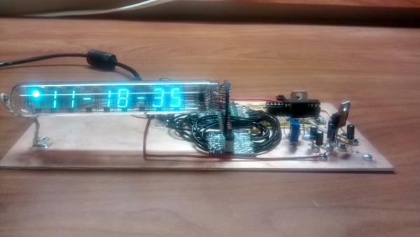
I know that and IV-18 based clock isn’t anything original. In fact, Adafruit used to sell a kit for this exact purpose. I don’t really care that it’s not original, because all vacuum tubes are cool, and doing all of the work yourself is really much cooler than using a kit. Also, I wanted to try my hand at Manhattan style construction. Manhattan style circuits are built on a copper ground plane, with little islands for every node of the circuit. Because of the ground plane, and because it has fewer parasitics than strip board or perfboard, Manhattan style construction is often used for radio frequency projects. My project isn’t a radio project, and the circuit probably would have worked just fine on a strip board, but Manhattan style construction gives a circuit a crude/retro look, which pairs nicely with a Russian vacuum tube.
If you wanna skip straight to the source code, the files are available here.
Driving the VFD
Originally I wanted to avoid using a VDF display driver. I wanted to use shift registers and decoders driven with my trusty MSP430G2553. Then I started reading the datasheet of the IV-18. The tube needs +50V on each of the segment pins that need to be lit and +50V on the pin corresponding to the digit. This means that I would need high-voltage PNP transistors for each segment and each digit,for a total of 17 transistors. I could use an 8-bit shift register to drive the segments, but I would have needed 9 bits to control the characters (8 characters + the AM/PM indicator character). I could have used an 8 bit decoder and and extra pin on my microcontroller for the AM/PM. This would mean I’d need 7 total pins, three for the shift register, three for the decoder and one for the AM/PM segment. This just wasn’t practical since I’d need to but the high voltage transistors anyway. I decided to go with the Max6921 vacuum florescent display driver, which is basically just a 20-bit high voltage shift register. Here’s a link to the datasheet.
As I mentioned before the microcontroller I’m using is the TI MSP430G2553. I bought several for my embedded systems class I took last semester so I have a bunch laying around. The core code for the real time clock is the same as in my Analog Gauge Clock project. It uses 1 Hz interrupts generated from the Watchdog timer to keep time based off a 32 kHz watch crystal. Here are the important bits of that code.
For more detail: MSP430 VFD Clock – Manhattan Style
About The Author
Ibrar Ayyub
I am an experienced technical writer holding a Master's degree in computer science from BZU Multan, Pakistan University. With a background spanning various industries, particularly in home automation and engineering, I have honed my skills in crafting clear and concise content. Proficient in leveraging infographics and diagrams, I strive to simplify complex concepts for readers. My strength lies in thorough research and presenting information in a structured and logical format.
Follow Us:LinkedinTwitter