
UPDATE: I eventually decided to use a single switching regulator that I found on digikey which is both awesome and well priced. See this blog post update about it.
My first DoorBell Mote prototype was working nicely and it allowed monitoring the door bell (while also triggering it remotely – toddlers love it). But I wanted more. On weekends the family likes to get a well deserved nap during the day and often those pesky solicitors ring the bell and wake everyone up. So naturally the doorbell has to be disabled also, without major effort or any disconnected wires. Sounds like the perfect addition to the Door Bell Mote. So I made a new revision and a proper PCB for this, below is the schematic with the changes and the proto PCB from OSHPark. Actually I made more changes to the schematic after putting together the PCB, so there are some differences. I’ve tried a LTV814H optocoupler for AC detection instead of the more expensive H11AA11, it works just as well, but both can be used on this PCB:
 More Awesome DoorBell Control
Modes of operation: detect and triggerThere are 2 regulators on this PCB. One is a 12V linear LM7812. The second is a 3.3V linear regulator getting input from the 12V LM output, both in TO220 packages. I know they are super inefficient to convert rectified 16VAC to DC voltages and the critics will stone me for doing this. But here’s the deal – the linears are about 50cents each and I had both among my junk parts. An efficient switching regulator is somewhere between $5-$10. The linears run somewhat warm. The 3.3V regulator only gets warm when I use the disable relay. So they can get warm but not hot, which is fine by me, it’s just a tradeoff. I might make a new revision where I have a single switching regulator such as this one, a drop in replacement for the LM linear regs.
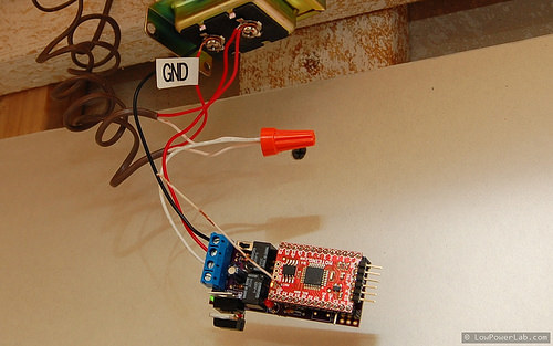
If I just want to use this as a bell detector and trigger a ring, I can wire it as before, 3 simple taps, into the first 3 terminals (“GND”, AC, and trigger). The terminals from the transformer are AC so there is no ground, but I marked one of the wires as “GND”, this is our virtual ground for the DC part of the circuit, the other provides our DC rectified output:
Modes of operation: detect, trigger and disable/enable
However the main purpose of this revision was to make it possible to disable the door bell convenienty from my smart phone when we want a quiet nap. For that there’s a second simple non-latching relay that will need to turn ON to disable the doorbell (see the schematic, it interrupts the wire going to the front door bell button). Below is the the wiring for this new mode, note the two white wires with the orange wire nut where we originally tapped to trigger the bell, now they become split and go into the bottom 2 terminals and through the disabling relay, which by default (turned OFF) has the two connected just as if they were connected with the wire nut. When the relay is turned ON, the two wires become disconnected, hence disabling the bell. I know a latching relay would have been a much more efficient choice here, but again in terms of simplicity and cost effectiveness this was the best compromise, and also I can use the same type of small relay as the other one.
For more detail: More Awesome DoorBell Control
About The Author
Ibrar Ayyub
I am an experienced technical writer holding a Master's degree in computer science from BZU Multan, Pakistan University. With a background spanning various industries, particularly in home automation and engineering, I have honed my skills in crafting clear and concise content. Proficient in leveraging infographics and diagrams, I strive to simplify complex concepts for readers. My strength lies in thorough research and presenting information in a structured and logical format.
Follow Us:LinkedinTwitter