
This is an ongoing project to control a number (currently 5) of Lamina Atlas high power (350-500mA) LEDs. Current progress includes:
- PCB artwork (in Eagle) with connections for 5 RGB LEDs.
- Firmware for a Microchip PIC16f887 microcontroller to interface between the FTDI 245R USB chip and a number of Texas Instruments TLC5940 constant current LED drivers.
- Python ctypes interface to libftdi.
- A simple Python interface to communicate color commands by USB
- Ongoing work includes an intuitive graphical user interface, music synchronization, and a reworking of the hardware to utilize switching constant current regulators.
See 500mA 5-channel RGB LED Controller / Driver, for an updated design.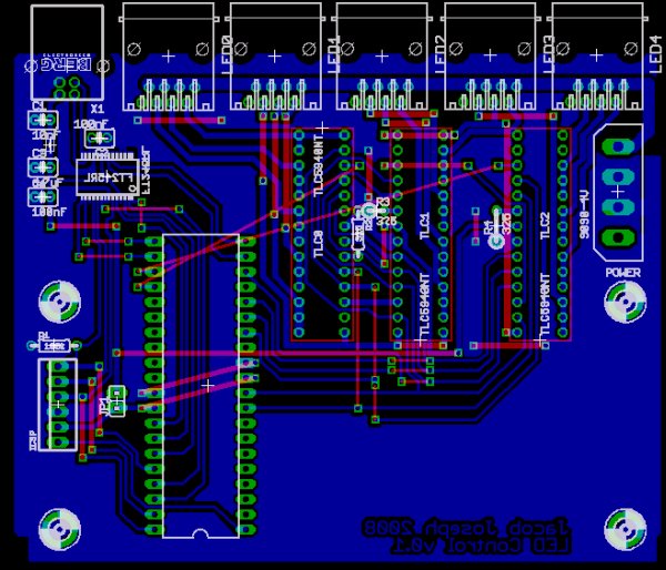
Motivation
Aside from mere novelty, this project was conceived for a use as a multicolor strobe controller during parties. The current implementation functions yields this, and effective general-purpose room lighting. This naïve implementation achieves approximately 100 frames per second, far in excess of necessity. Effective music synchronization is still in progress, as is a graphical interface.
Hardware
The Lamina Atlas LEDs are rated with an absolute maximum current of 700mA per color, though all output specifications are measured at 350mA. To simplify the number of components, this design uses three TLC5940 outputs in parallel per LED color, achieving 360mA (3x120mA). It is now my understanding that these LEDs are well-rated for 500mA use, but I’ll likely switch to separate amplification for such an increase rather than adding further TLC5940 chips.
All power for devices other than the LEDS is drawn from the USB bus, so do use a powered hub. Though the devices use small amounts of power, I have only eyeballed that the power utilization stays within the USB spec. Input voltage for the LEDS is provided by the 12V line of a standard. I use a computer power supply. Any supply of more than 8-9V should be enough for the maximum forward voltage of the Lamina LEDs and TLC5940 drivers.
Warning: The TLC5940 chips cannot sink as much current as this design would have you believe. While each chip channel can sink 120mA, not all channels may be used at once unless the input voltage is very low. External resistors are required. To remain within the TLC5940 spec, drop no more than about 1V per color channel at maximum intensity. That is, use external resistors, in the 8-15 ohm range in series on each channel until the TLC5940 chip sinks at 1V.
For good measure, I do use a heatsink on the TLC5940 chips. Switching constant current regulators such as the Supertex HV9910 would make the controller more efficient, and resolve this oversight.
I’ve etched only with a single-layer board, with wires on the top layer. If a double-layer board were to be used, a few crossed traces on the top layer would need to be re-routed.
Firmware
This code is written for a 16F887 PIC, though it could easily be ported to other chips. Currently, only one-way (write from computer) communications is functional. Much of the code needed to read is written, though untested.
Functional Overview
A tight loop in main monitors the 245R RD line, indicating new input data. The first byte defined a command, followed by a variable-length set of parameters, which are clocked in immediately. Global state bits are then (atomically) set if, for example, a color update should be performed.
The TLC5940 clocking is performed first by the clkout pin, at OSO/4. Blanking, and all communications with the TLC5940 chips must be coordinated such that commands complete before a blank cycle. These are handled by an interrupt driven by Timer 1. Note that commands are processed only at the next interrupt cycle, introducing some latency.
A few primary commands are fully implemented:
- 0x02
- Raw grayscale data: 16 x 12 bits = 24 bytes ordered MSB first
- 0x03
- Raw dot correction data: 16 x 6 bits = 12 bytes ordered MSB first
- 0x80
- Reset command input. Send 24 bytes to be sure to exit any read loops.
- 0x81
- Disable GIE (global interrupt enable): Halts the BLANK interrupt, disabling the PWM drivers. Turns lights off.
- 0x82

- Enable GIE: Restart the BLANK interrupt, resuming the PWM drivers. Turns lights on.
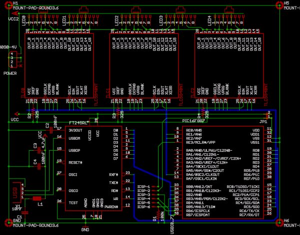
Only after etching this board did I obtain a Pickit 2 programmer. This programmer allows in circuit debugging, but I had used the ICD pins, RB6 and RB7, for data communications. If RD6 and RD7 are substituted for RB6 and RB7 on the PCB, an ICD can be used. Search on ICD hack in main.c With a little effort in Eagle, PORTD should be substituted for PORTB. Myself, I’ll get around to this when I need another PCB.
FTDI Python Interface
- Code: libftdi.py
This is a quick-and-dirty Python interface to the libFTDI library. It utilizes ctypes. Only the subset of functions needed for this project are implemented. Others from the library may be easily added.
For more detail: Misc Projects : High Power RGB LED Controller
About The Author
Ibrar Ayyub
I am an experienced technical writer holding a Master's degree in computer science from BZU Multan, Pakistan University. With a background spanning various industries, particularly in home automation and engineering, I have honed my skills in crafting clear and concise content. Proficient in leveraging infographics and diagrams, I strive to simplify complex concepts for readers. My strength lies in thorough research and presenting information in a structured and logical format.
Follow Us:LinkedinTwitter