
| RS232 EIA232F TTL and USB Adaptor Examples Tx and Rx Baud Rate, Misc Asynchronous Tx Loop-Back Test $50 Robot UART |
What is the UART?
The UART, or Universal Asynchronous Receiver / Transmitter, is a feature of your microcontroller useful for communicating serial data (text, numbers, etc.) to your PC. The device changes incoming parallel information (within the microcontroller/PC) to serial data which can be sent on a communication line.
 Adding UART functionality is extremely useful for robotics. With the UART, you can add an LCD, bootloading, bluetooth wireless, make a datalogger, debug code, test sensors, and much more!
Understanding the UART could be complicated, so I filtered out the useless information and present to you only the useful need-to-know details in an easy to understand way . . . The first half of this tutorial will explain what the UART is, while the second half will give you instructions on how to add UART functionality to your $50 robot.
What is RS232, EIA-232, TTL, serial, and USB?
These are the different standards/protocols used from transmitting data. They are incompatible with each other, but if you understand what each is, then you can easily convert them to what you need for your robot.
RS232
RS232 is the old standard and is starting to become obsolete. Few if any laptops even have RS232 ports (serial ports) today, with USB becoming the new universal standard for attaching hardware. But since the world has not yet fully swapped over, you may encounter a need to understand this standard.
Back in the day circuits were noisy, lacking filters and robust algorithms, etc. Wiring was also poor, meaning signals became weaker as wiring became longer (relates to resistance of the wire). So to compensate for the signal loss, they used very high voltages. Since a serial signal is basically a square wave, where the wavelengths relate to the bit data transmitted, RS232 was standardized as +/-12V. To get both +12V and -12V, the most common method is to use the MAX232 IC (or ICL232 or ST232 – different IC’s that all do the same thing), accompanied with a few capacitors and a DB9 connector. But personally, I feel wiring these up is just a pain . . . here is a schematic if you want to do it yourself (instead of a kit):
EIA232F
Today signal transmission systems are much more robust, meaning a +/-12V signal is unnecessary. The EIA232F standard (introduced in 1997) is basically the same as the RS232 standard, but now it can accept a much more reasonable 0V to 5V signal. Almost all current computers (after 2002) utilize a serial port based on this EIA-232 standard. This is great, because now you no longer need the annoying MAX232 circuit!
Instead what you can use is something called the RS232 shifter – a circuit that takes signals from the computer/microcontroller (TTL) and correctly inverts and amplifies the serial signals to the EIA232F standard. If you’d like to learn more about these standards, check out this RS232 and EIA232 tutorial (external site).
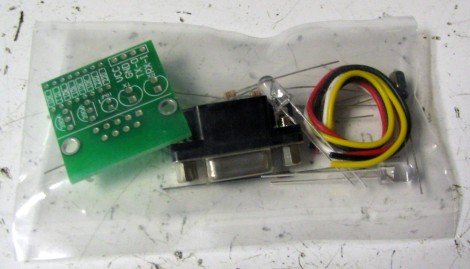
The cheapest RS232 shifter I’ve found is the $7 RS232 Shifter Board Kit from SparkFun. They have schematics of their board posted if you’d rather make your own.
And this is the assembled image. Notice that I added some useful wire connectors that did not come with the kit so that I may easily connect it to the headers on my microcontroller board. Also notice how two wires are connected to power/ground, and the other two are for Tx and Rx (I’ll explain this later in the tutorial).
TL and USB
The UART takes bytes of data and transmits the individual bits in a sequential fashion. At the destination, a second UART re-assembles the bits into complete bytes.
You really do not need to understand what TTL is, other than that TLL is the signal transmitted and received by your microcontroller UART. This TTL signal is different from what your PC serial/USB port understands, so you would need to convert the signal.
You also do not really need to understand USB, other than that its fast becoming the only method to communicate with your PC using external hardware. To use USB with your robot, you will need an adaptor that converts to USB. You can easily find converters under $20, or you can make your own by using either the FT232RL or CP2102 IC’s.
 Signal Adaptor Examples
Without going into the details, and without you needing to understand them, all you really need to do is just buy an adaptor.
For example:
TTL -> TTL to RS232 adaptor -> PC
TTL -> TTL to EIA-232 adaptor -> PC
TTL -> TTL to EIA-232 adaptor -> EIA-232 to USB adaptor -> PC
TTL -> TTL to USB adaptor -> PC
TTL -> TTL to wireless adaptor -> wireless to USB adaptor -> PC
If you wanted bluetooth wireless, get a TTL to bluetooth adaptor, or if you want ethernet, get a TTL to ethernet adaptor, etc. There are many combinations, just choose one based on what adaptors/requirements you have. For example, if your laptop only has USB, buy a TTL to USB adaptor as shown with my SparkFun Breakout Board for CP2103 USB:
For more detail: MICROCONTROLLER UART TUTORIAL
About The Author
Ibrar Ayyub
I am an experienced technical writer holding a Master's degree in computer science from BZU Multan, Pakistan University. With a background spanning various industries, particularly in home automation and engineering, I have honed my skills in crafting clear and concise content. Proficient in leveraging infographics and diagrams, I strive to simplify complex concepts for readers. My strength lies in thorough research and presenting information in a structured and logical format.
Follow Us:LinkedinTwitter