
I’m always amazed at the new technology that is constantly coming out that allows hobbyists like myself access to powerful and cheap microcontrollers like the Arduino or chipKIT development boards. They are easy to program and easy to use, but sometimes the code can get a little bit long and we look at it and think “There has to be a better/faster/easier/shorter way to write this.” There are a few ways to simplify sketches, like using arrays and for() loops to iterate through assigning pin numbers to variables, but one of my favorites is to assign the 1’s and 0’s directly to the registers on the chip. This happens in the background when you compile and upload your sketch to your microcontroller. Each instruction and it’s associated parameters are broken down into a simpler language called Assembly (AVR instruction set for ATMEL chips, MIPS instruction set for PIC chips), and Assembly instructions are designed to directly manipulate the bits in registers. Now, you can take the time to learn Assembly and a new IDE to implement it, or, if your instructions are simple and clear, you can avoid the extra cost of space and time by skipping over the instruction conversion process and read/write data directly to/from the registers using standard IDE instructions that you are familiar with.
Step 1: So What Is a Register?
Wait, what’s a register you ask? In short, it’s a chunk of memory usually consisting of anywhere from 8 to 64 bits of data. Each bit is assigned a value of 1 or 0, and the value of each bit in the MANY different registers in a microcontroller tell the rest of the system what to do and when to do it. Most of the registers in the ATMEGA328P chip on the Arduino are 8-16 bits. The chipKIT boards use PIC processors, and they are usually 16-32 bit registers.There is a LOT more I could go into regarding registers, but it’s better left to another day. Wikipedia has a good explanation as well.
You can think of a register like you do an array when you write a piece of code in your favorite coding language, except that each element is a single bit, not a collection of bits that make up the int or char you defined. Also, just like arrays, the count starts at 0, not 1. So an 8-bit register (let’s call it myRegister for kicks) has 8 bits total, numbered from 0 to 7. So if we see a pin on our microcontroller assigned to bit myRegister[6], we know that the 7th (second to last) bit is the one we need to manipulate. It can be tough to keep straight, but it’s important. I’ll try and clarify it more later, probably to the point of overkill.
Some things to keep in mind – While register manipulation is a perfectly viable programming option, I don’t really recommend it unless you are extremely confident in your abilities and you are totally out of memory on your chip or need to free up some extra clock cycles. Oftentimes there are a lot of checks that happen in the background when you use the standard functions and libraries to assign I/O direction and values to the pins. It can get tricky keeping all of that stuff straight, and may not be worth the time and effort it takes to re-write your code using registers. That being said, the examples I will show you are simple and basic in the extreme so anybody can use them, regardless of experience. They will definitely take less memory and process faster than if you were to use the standard functions. But you need to be extremely careful when you manipulate the registers directly, and quadruple check your statements. It would be tough to damage the chips manipulating the registers incorrectly, but it can be much harder to debug when it doesn’t work right, most often because you wrote the wrong value to the wrong register and/or bit. The standard functions and libraries are there for a reason. They take more memory and processing time, but are usually more user friendly. Last thing, don’t forget that the performance parameters for each pin don’t change (e.g. current sourced/sunk, voltages, etc.) when you use the registers. Don’t blame me when you try and drive a 2A motor directly from pin 10 and it smokes your chip. That’s on you because you should know better anyway.
Step 2: Making Code Shorter the Easy Way…
Let’s start off with a simple sketch that checks the state of one of 4 buttons and ties that value to one each of 4 LEDs. Press any button(s), the corresponding LED(s) light up.
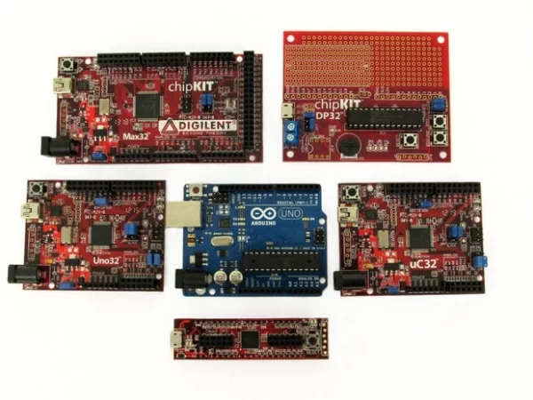
I’ve included pin-mapping for the 5 different boards shown here, the chipKIT Max32, DP32, Uno32, Uc32 and CMOD boards and the Arduino UNO:
Now, when I first started writing code, it was always the longest code I could think of because I didn’t know any better. I imagine it would have looked something like this:
/* This a long, pin-by-pin version
   of mapping 4 switches to 4 LEDs*/

//pins for Uno32/uC32  : Max32 : DP32 : CMOD : UNO
int led_1 =    26; //  :   34  :  5   :  20  : 4
int led_2 =    27; //  :   35  :  6   :  21  : 5
int led_3 =    28; //  :   36  :  7   :  22  : 6
int led_4 =    29; //  :   37  :  8   :  23  : 7

int btn_1 =    30; //  :   30  :  0   :  35  : 8
int btn_2 =    31; //  :   31  :  1   :  36  : 9
int btn_3 =    32; //  :   32  :  2   :  37  : 10
int btn_4 =    33; //  :   33  :  3   :  38  : 11

void setup()
{
  pinMode(led_1, OUTPUT);
  pinMode(led_2, OUTPUT);
  pinMode(led_3, OUTPUT);
  pinMode(led_4, OUTPUT);

  pinMode(btn_1, INPUT);
  pinMode(btn_2, INPUT);
  pinMode(btn_3, INPUT);
  pinMode(btn_4, INPUT);
}

void loop()
{
  if ((digitalRead(btn_1) == HIGH) &&
      (digitalRead(btn_2) == LOW) &&
      (digitalRead(btn_3) == LOW) &&
      (digitalRead(btn_4) == LOW))
  {
    digitalWrite(led_1, HIGH);
    digitalWrite(led_2, LOW);
    digitalWrite(led_3, LOW);
    digitalWrite(led_4, LOW);
  }
  else if ((digitalRead(btn_1) == LOW) &&
           (digitalRead(btn_2) == HIGH) &&
           (digitalRead(btn_3) == LOW) &&
           (digitalRead(btn_4) == LOW))
  {
    digitalWrite(led_1, LOW);
    digitalWrite(led_2, HIGH);
    digitalWrite(led_3, LOW);
    digitalWrite(led_4, LOW);
  }
  else if ((digitalRead(btn_1) == LOW) &&
          (digitalRead(btn_2) == LOW) &&
          (digitalRead(btn_3) == HIGH) &&
          (digitalRead(btn_2) == LOW))
  {
    digitalWrite(led_1, LOW);
    digitalWrite(led_2, LOW);
    digitalWrite(led_3, HIGH);
    digitalWrite(led_4, LOW);
  }
  else if ((digitalRead(btn_1) == LOW) &&
          (digitalRead(btn_2) == LOW) &&
          (digitalRead(btn_3) == LOW) &&
          (digitalRead(btn_4) == HIGH))
  {
    digitalWrite(led_1, LOW);
    digitalWrite(led_2, LOW);
    digitalWrite(led_3, LOW);
    digitalWrite(led_4, HIGH);
  }
  else
  {
    digitalWrite(led_1, LOW);
    digitalWrite(led_2, LOW);
    digitalWrite(led_3, LOW);
    digitalWrite(led_4, LOW);
  }
}
(You can use this with just a few changes to the pin assignments. Copy and comment/uncomment as needed. These pins were chosen because it will make it easier to manipulate the registers later. More code will be added later on for each of these boards.)
Top to bottom, this sketch is 73 lines (not counting comments), and using MPIDE will require 6664 bytes of memory for the chipKIT Uno32 and 1402 bytes for the Arduino UNO.
Now, let’s look at a modified version, this time using some for() loops to do the repetitive stuff, and some nested digitalRead() and digitalWrite() commands to assign pin states.
/* This is a more concise version of
   mapping 4 switches to 4 LEDs*/

//pins for Uno32/uC32
int led[] = {26,27,28,29};
//Max32 : {34,35,36,37};
//DP32 : {5,6,7,8};
//CMOD : {20,21,22,23};
//UNO : {4,5,6,7};

int btn[] = {30,31,32,33};
//Max32 : {30,31,32,33};
//DP32 : {0,1,2,3};
//CMOD : {35,36,37,38};
//UNO : {8,9,10,11};

void setup()
{
  for (int i = 0; i < 4; i++)
  {
    pinMode(led[i], OUTPUT);
    pinMode(btn[i], INPUT);
  }
}

void loop()
{
  for (int i = 0; i < 4; i++)
  {
    digitalWrite(led[i], digitalRead(btn[i]));
  }
}
This sketch is noticeably shorter. In fact, it’s less than a third at 20 lines w/o comments. It does take a bit less space in memory (6324 bytes for chipKIT, 1074 bytes for Arduino), but the only real benefit is that the sketch takes fewer lines. The instruction set in memory is roughly the same. The compiler still has to search for and load the pinMode(), digitalRead() and digitalWrite() commands from the background library files. These are preset in size, so if you use them even once the converted Assembly instructions must be loaded into the chip memory.
So even if we shorten the code, it’s clear that it may not save much space on the chip. Let’s fix that.
Step 3: ChipKIT Microcontrollers With PIC32 Chips
Let’s start off with my personal favorite family of microcontrollers, the chipKIT. (If you wish, the shortened sketch for the Arduino UNO is in the next step, but the logic will be explained here.) Using Microchip’s PIC32 32-bit processors, the chipKIT has far more memory, almost twice as many I/O pins, and runs much faster than the comparable Arduino boards, so if you need that extra oomph, I would recommend you look into getting one. (It’s also a good idea to familiarize yourself with as many devices as possible to make yourself as useful as possible to an employer, if that is your goal.)
Every I/O pin on a microcontroller is connected to at least three different registers. (Pins that have several functions associated with them have several more, e.g. PWM and I2C/SPI/UART.) Of the three we are concerned with here, one is the TRISx register that determines whether the pin is to be an input or an output, where “x” designates which TRIS we are working with since there are several (the pinMode() function sets TRISx). Setting a bit in TRISx as a 1 will set the corresponding pin as an input, and it follows that setting it as a 0 will set the pin as an output. The next is the LATx register, which is where we assign a pin set as an output to be HIGH (1) or LOW (0)(digitalWrite() sets LATx). The last is the PORTx register, and this is where we can read the current state of the pin when it is set to an input (digitalRead() reads PORTx). A ‘1’ bit in PORTx indicates that the corresponding input pin is detecting a logic high value. Each register is updated with the peripheral bus clock while the code is running so your input/output status will be real time. Technically you can read/write to all three of these registers, but you really only want to write to the TRISx register one time in your setup() statement at the beginning of your sketch. You can retrieve the state of both LATx and PORTx and use that data as needed, but writing a 1 to the LATx register for a pin that is designated as an input will do nothing because it can’t output (you set it up as an input with the TRISx register). Confused yet?
Keep on trucking, it will make sense.
To initialize TRISx in setup(), you first need to know which register and bits are tied to which pins. Using the pin-out table (see attached .pdf file below) for the chipKIT Uno32, we can see that pins 26→33 are very nicely mapped to register E, bits 0→7. (I find it easier to use sequential bits in a register. Later we will need to do some bitwise operations, and it simplifies things.) It should make sense then that we will be setting TRISE, bits 0→7. Looking back at the code, we determined that pins 26→29 would be LEDs and 30→33 would be the switches. Pins 26→29 map to TRISE bits 0→3. LEDs are output, so bits 0→3 get a 0. Pins 30→33 map to TRISE bits 4→7. Switches are input, so bits 4→7 get a 1. Looking at the register bit-by-bit, we need the last 8 bits of TRISE to be 1111 0000. Take a second to make sure you understand why.
We could just assign the value, using either a hex value of 0xF0 or a binary value of 0b11110000, directly to TRISE with the line
TRISE = 0xF0;
but we run the risk of inadvertently changing the other more significant bits in the register. Remember that we are dealing with 16-32 bit registers with the PIC32. (From table 4-27 on pg 73 of the datasheet for the PIC32MX320F128, I know that TRISE only allows me access to the 10 least significant bits, but I choose to protect the entire 16-bit register as a matter of good practice.) We need to ensure that we are only setting the exact bits we need while leaving the other bits in whatever state they are currently in so we don’t accidentally jack stuff up. To do this, we use a technique called masking and some bitwise logic operators. Let’s say that TRISE starts with a value of 0b1101 0010 1001 1011. Using the bitwise logical OR operator “|”, we OR TRISE with 0b0000 0000 1111 0000 (0x00F0). When we OR, wherever there is a ‘1’, the result will always be a one. If there is a ‘0’, the result will be determined by the state of the other operand. Back to our example, if we OR 0b1101 0010 1001 1011 with 0b0000 0000 1111 0000 we end up with 0b1101 0010 1111 1011. We can see that bits 4→7 are now all 1’s, which is what we wanted.
Using similar logic and the AND operator, we then take TRISE and AND it with 0b1111 1111 1111 0000. Any time we AND with a ‘0’, the result is always a 0. ANDing with a ‘1’ results in the state of the other operand. So we have 0b1101 0010 1111 1011, AND it with 0b1111 1111 1111 0000 and the result is 0b1101 0010 1111 0000. The last four bits, 0→3, are now 0’s, which is again what we wanted. Note that the 8 most significant bits are left untouched. The two operations (AND/OR) can be reversed without affecting the outcome. The two lines of code for this are as follows:
TRISE = TRISE | 0x00F0; //0b0000 0000 1111 0000
TRISE = TRISE & 0xFFF0; //0b1111 1111 1111 0000
If it makes it easier, the hex/bin values can be assigned as int variables before setup().
Now that we have TRISE set, (pinMode()), we can now write our loop() statement. Looking back at the shorter, simplified version of the code in the last step, notice that we are reading the state of the input pin (digitalRead() = PORTE) and mapping it to the output pin (digitalWrite() = LATE). So LATE = PORTE, but with one slight adjustment. Remember that the buttons are tied to PORTE bits 4→7 and the LEDs are tied to LATE bits 0→3. If we write LATE = PORTE, we are writing the state of PORTE bits 4→7 to LATE bits 4→7, not LATE bits 0→3. We need to shift the PORTE data over to the right 4 spaces so that it matches the bit placement in LATE. Put another way, if PORTE reads 0b0010 1101 1111 0000, bits 4→7 are all high. We shift the data right by 4 bits (0b0000 0010 1101 1111) and assign this new value to LATE, setting bits 0→3 high and all 4 LEDs light up. A bitwise shift is simple for the processor to do and will not affect the current data present on PORTE. The PORTE data is actually copied to a temporary register and that is the one that is manipulated if needed. The only way for PORTE to change values is to change the button states. Here’s the line of code:
LATE = PORTE >> 4;
You’ll notice that I’m not trying to do any masking here when assigning PORTE to LATE. The reason is that LATE isn’t used for anything but output, and if the specific bit in TRISE is not set as an output, a 1 on that bit in LATE won’t have any effect. The same is true for PORTE when trying to read it. You can attach a button to any bit in PORTE, but unless you assign PORTE as an input in TRISE, pressing the button won’t change the value in the register. Any changes are errant and random because the pin has no pull-up/-down resistor.
By using 4 sequential bits in PORTE, extracting the data is a simple matter of bitwise shifting, which is a ridiculously cheap operation as far as the chip is concerned in terms of time and resources needed. If we had used scattered bits and registers around the board, we would need to do some masking and ANDing and ORing, but we could get the data. We have also avoided calling pinMode(), digitalRead(), and digitalWrite(), so our code should take up less space on chip since those background files don’t have to be loaded. Let’s see how much space we need now.
Here’s the code:
/* chipKIT register manipulation with 4 switches and 4 LEDs
* Uno32/uC32 - 4 switches on pins 30-33, 4 LEDs on pins 26-29.
* Max32 - 4 switches on pins 30-33, 4 LEDs on pins 34-37.
* DP32 - 4 switches on pins 0-3, 4 LEDs on pins 5-8.
* CMOD - 4 switches on pins 35-38, 4 leds on pins 20-23.
*/
void setup()
{
// Uno32, Uc32, and Max32
 TRISE = TRISE & 0xFFF0; // digital pins 26->33 (37->30 Max32) map to
 TRISE = TRIES | 0x00F0; // register E, bits 0->7, respectively. A '1'
			 // defines the pin as input, '0' as output.
			 // We use the bitwise AND (&) first to set bits
			 // 0-3 as 0 (output) and then bitwise OR (|) to
			 // set bits 4-7 as input. This allows the remaining
			 // bits to be unaffected and avoid unwanted operation
			 // and only set the 8 pins we want. You could write
			 // TRISE = 0xnnnn to set just the bits you want
			 // (where n is any hex digit) but there is no way
			 // of knowing how the other bits in the register
			 // will be affected. It may do nothing, it may not.

// DP32 only
// TRISB = TRISB & 0x17FF; // digital pins 0->3 and 5->8 map to
// TRISB = TRISB | 0x03A0; // register B, bits 5,7->9 and 11,13->15
			   // respectively. The same logic as above applies
			   // here with setting the TRIS register.

// CMOD only
// TRISB = TRISB & 0xFFF0; // digital pins 20->23 and 35->38 map to register,
// TRISB = TRISB | 0x01E0; // bits 0->3 and 5->8 respectively. The same logic
			   // as above applies here with setting the TRISx
			   // register.
}

void loop()
{
// Uno32, Uc32, and Max32
 LATE = PORTE >> 4; // write the status of the switches on PORTE to
                    // the LEDs on LATE, but bit shifted right by 4 bits.
                    // So RE7-4 map to RE3-0.

// DP32 only
// LATB = PORTB << 6;

// CMOD only
// LATB = PORTB >> 5;
}
This code takes 10 lines w/o comments, and most of that are the required setup() and loop() structures. There are only 3 lines of actual code. 3.
Compiling this in MPIDE for the chipKIT Uno32 requires 4792 bytes, a reduction of 1532 bytes from the shorter version in the previous step that cost 6324 bytes.
The next step shows the same code but specifically for the ATMEL chip.
Attachments
Step 4: Arduino Microcontrollers With ATMEL Chips
As mentioned previously, the background Assembly languages used to program the PIC32 and ATMEL chips are different. If you then jump to the conclusion that the register names are different, you would be right.
I won’t go as deep into the logic explanation here, but there are some critical differences that you must keep in mind. Refer back to the previous step for the in depth explanation of the logic.
First, the directional register that sets the I/O state of the pin is called DDRx, where x designates the register (pinMode() sets DDRx). To set the pin as an output, you need to write a 1 to the corresponding bit in DDRx. Writing a 0 to DDRx will set the pin as an input. Next is the PORTx register, which determines whether a pin set as an output is HIGH (1) or LOW (0) (digitalWrite() sets PORTx). Last is PINx, which allows you to read data present on the pin it it is set as an input (digitalRead() reads PINx). A ‘1’ in the PINx register indicates that there is a signal present on that pin.
Looking at the Arduino UNO (see .pdf below, source here), I decided to use 4 LEDs on pins 4→7 that map to register D, bits 4→7. We set register D4→7 as outputs by ORing with 0b1111 0000, setting those four bits as 1’s. I put 4 switches on pins 8→11, which map to register B, bits 0→3. We set register B0→3 as inputs by ANDing with 0b1111 0000, setting those four bits as 0’s. The following code goes in our setup() statement:
DDRD = DDRD | 0xF0; //0b1111 0000
DDRB = DDRB & 0xF0; //0b1111 0000
Looking at the register bits again, we see that the switches are assigned to bits 0→3 and the LEDs to bits 4→7. If we just assign the state of PINB directly to PORTD, we will be setting PORTD bits 0→3, not bits 4->7 and the LEDs won’t light up. We fix this with a bitwise shift to the left by four spaces. The code for our loop() statement looks like this:
PORTD = PINB << 4;
Here’s the complete code:
// Arduino register manipulation with 4 switches
// on pins 8-11, 4 LEDs and resistors on pins 4-7

void setup()
{
DDRD = DDRD | 0xF0; // digital pins 4-7 map to register D,
                    // bits 4-7. 0xF0 = 0b1111 0000 where
                    // a 1 defines the pin as output. Using
                    // the bitwise OR (|) allows the remaining
                    // bits to be unaffected and avoid
                    // unwanted operation and only set
                    // the 4 pins we want. You could write
                    // DDRD = 0xnn, (where n is any hex digit)
                    // but there is no way of knowing how
                    // the other bits will be affected.
                    // It may do nothing, it may not.

DDRB = DDRB & 0xF0; // digital pins 8-11 map to register B0-3.
                    // Using 0xF0 again, but now 0 is an input.
                    // We use bitwise AND (&) to leave
                    // the remaining bits in the register alone.
}
void loop()
{
PORTD = PINB << 4; // write the status of the switches on
                   // PINB to the LEDs on PORTD, but bit
                   // shifted left by 4 bits. So RB3-0 map
                   // to RD7-4.
}
Again 10 lines of code, and only 3 do something. That’s it.
Compiling this with MPIDE takes just 470 bytes of memory, a reduction of 604 bytes from the shorter version in step 2 that cost 1074 bytes and used pinMode(), digitalWrite() and digitalRead().
Attachments
Step 5: So What’s the Point Then?
It should be pretty clear that writing directly to the registers can save space in your chip memory. The shortened sketch also takes less time to execute simply because there are no libraries to look up for each function call. For the vast majority of applications, this won’t have any real use because eliminating one function like pinMode() won’t save much space or time in a complex sketch. However in some applications processing time is a huge concern, and shortening the amount of wasted time in the library files allows for more clock cycles to be available for other things. What I mean by that is that even if you must include a library function, and therefore take up space in memory with it, if you don’t call it very often and instead use the registers directly, at least you save time (but not space) by not looking it up.
Another option is the ability to use pins in ways they may not have been originally intended, but without any side effects. For example, the pins associated with PWM on the chipKIT Uno32 have an additional register associated with them that ties into the output compare module (OCMP) called the output compare register (OCxR). The OCMP has some more registers that deal with the timing of the PWM signal, but the OCxR is the actual signal output register, similar to the LATx (PIC32) or PORTx (ATMEL) registers. The PWM period is calculated by multiplying… (easy but confusing math stuff here) … and that value is input into the period register (PRy). PRy tells the timer register (TMRy) that drives the specific OCMP when to reset back to 0, but you have to add an extra 1. The duty cycle is then written to the secondary compare register (OCxRS), which is basically a buffer because this value is almost immediately transferred to the compare (OCxR), but you can’t write it directly because OCxR is read only.
Example: if PRy has a value of 5 and OCxRS is loaded with a value of 2, OCxR is first loaded with 2 as well. TMRy starts counting at 0. At 1, OCx outputs a high value and stays there. At time 2, nothing changes, OCx has been high for 1 count. At time 3, OCx drops low since it has been high for 2 counts. At time 3, 4 and 5 nothing changes but TMRy = PRy, so it resets and then starts back at 0 on the next count. 1 clock tick passes, which is count 0 again, and at count 1, OCx outputs high again. Here’s figure 16-18 from Section 16: Output Compare of the PIC32 family reference manual:
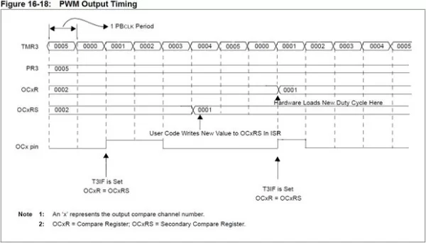
Setting PRy to 5 and OCxRS to 2 actually gives a duty cycle of 33% (2/6) and not 40% (2/5). That’s where that extra 1 comes in. It gets added to the value of PRy. This is just a simple example, and if PRy and OCxRS were much larger, the difference in %’s would be much, much smaller.
Well, that was simple wasn’t it? Yeah, no. I could hear the gears grinding to a halt at “For example…” You should have seen the look on my classmates faces when the professor showed us this the first time. But this is why we have libraries. All of this stuff is handled by the libraries when we tell the servo to turn at a certain speed or we want to play a melody with different tones. But 1) we are limited to only being able to use the PWM pins, and 2) libraries take up space in memory. What do we do if we need more PWM options? Use the registers.
The following sketch is a simple tone generator. I’m not going to do a servo example because I don’t recommend using servos without the servo.h library, though with some work it is definitely possible. It’s way too easy to over extend the servo beyond it’s internal stops. If you want to do it, you’ll have to write all of the background stuff that servo.h handles in your sketch, but longer sketches will result in different PWM periods because each line takes a bit of time.
Before we see the sketch, some quick simple math. First determine the output frequency you want. Divide 1 by your frequency to get your period, and then divide that in half. Make sure that value is in microseconds, then put that value in both of the delayMicroseconds() function implementations. If we want to generate a duty cycle other than 50%, multiply your period value by the duty cycle percentage you want high. Enter that new value into the delayMicroseconds() function inside the if() statement. Enter the remainder in to the delayMicroseconds() function inside the else statement.
Example: You want an output of 1kHz. 1/1000Hz = 1 millisecond = 1000 microseconds = period. 1000μs/2 = 500 μs ⇒ delayMicroseconds(). If you want 60% duty cycle: 1000μs * 60% = 600 μs ⇒ if() statement delayMicroseconds() value. 1000μs – 600μs = 400μs ⇒ else statement delayMicroseconds() value. Nice and easy.
Here’s the tone generator code:
// Simple tone generator not using preset PWM
// pins but using register manipulation

bool state = true;

void setup()
{
  // chipKIT only
  // set register E, bit 0 as an output (0)
  // pin 26 Uno32/uC32; pin 37 Max32
  TRISE = TRISE & 0xFFFE; // 0b1111 1111 1111 1110

  // Arduino only
  // set register B, bit 0 as an output (1)
  // pin 8 UNO
  // DDRB = DDRB | 0x01; // 0b0000 0001
}

void loop()
{
  if (state)
  {
    // chipKIT only
    LATE = 0x0001;

    // Arduino only
    // PORTB = 0x01;

    state = false;
    delayMicroseconds(500);
  }
  else
  {
    // chipKIT only
    LATE = 0x0000;

    // Arduino only
    // PORTB = 0x00;

    state = true;
    delayMicroseconds(500);
  }
}
Below you’ll find o-scope images of the output, first from the chipKIT Uno32…
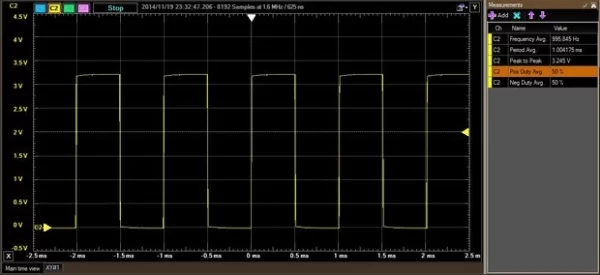
…and then from the Arduino UNO.
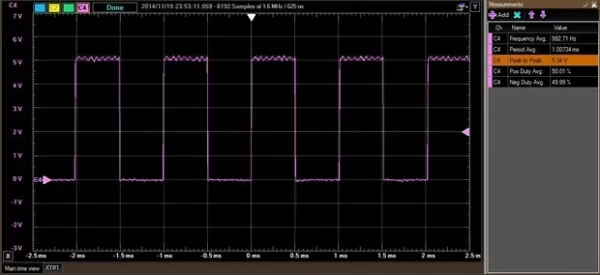
Crazy enough, these images were generated using the register manipulation sketch as shown above, and when I tested the standard function sketch, the exact same image popped up. Weird, right? So I figured I would spare you having to waste time looking at a duplicate. I also have no idea why the Arduino UNO is quite unstable at peak output, so if anybody has any legitimate explanation, please clarify in the comments.
Step 6: EOL;
Register manipulation is easy, cheap, and kind of fun. It’s always nice to add something new to your arsenal of coding tricks, so hopefully this wasn’t too hard to follow. I struggled with it for a few weeks in class, but then it just clicked and I actually prefer to write code for my microcontrollers using the MPLAB IDE in MIPS Assembly language over MPIDE for the PIC32 boards. I’m not familiar with AVR Assembly, but I’ve given it a cursory glance and it wouldn’t be that hard to learn. I am however unfamiliar with an IDE that will allow you to write to ATMEL chips in AVR Assembly, so if you know of a quality IDE, please give a clear reference in the comments. Thanks so much.
As always, thanks for reading. If you have questions, please ask them in the comments below, though PM’s are always welcome as well. You just never know when someone else has the same question and that way we can all learn and help each other get better. Have fun building!
Also, please check out the Digilent blog where I contribute from time to time.
Source: Microcontroller Register Manipulation
About The Author
Muhammad Bilal
I am a highly skilled and motivated individual with a Master's degree in Computer Science. I have extensive experience in technical writing and a deep understanding of SEO practices.