Matrix keypads are very useful when designing certain systems which needs user input. These keypads are constructed by arranging push button switches in rows and columns as shown in Fig.1. Scanning keypad to detect pressed keys involves several steps and there are several methods to achieve this. The method presented here is capable of detecting more that one key press at time and encode that information in single 16bit (unsigned int) variable. For example this keypad scan routine can be used to detect key presses like CTRL+C in computer keypads.
The example program given in this page uses schematic diagram shown and uses Microchip C18 compiler. The example program will display number of key pressed in 7 segment LED display. If more than one key pressed at a time, it will display ‘H’ character. Schematic diagram shown also shows ICD2 connection which is optional and you can use any programmer/debugger to upload this program to PIC.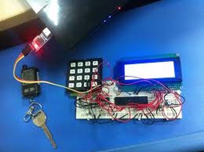
Example program has function “ unsigned int ScanKeypad(void) ” where you can use this in your codes provided that keypad is connected to PICs pins as given in schematic bellow.
Keypad Scan Algorithm.
Scanning any matrix keypad involves several steps. The operation algorithm of example ScanKeypad(void) routine given here is explained in following steps. This routine uses logic operations instead of assigning values to ports because we can change only necessary pins while not touching unused pin values. This is very useful when you have other IP or OP devices connected to remaining pins of same port used by keypad. i.e. PORTB4:7 and PORTD0:3 in this example. ScanKeypad(void) routine should be called only after setting ROW pins and OP and Column pins as IP from main program via setting and clearing appropriate TRIS bits (shown in example code).
1. ScanKeypad(void) routine supply logic 0 (0V or GND) to all 4 keypad row wires named R1, R2, R3 and R4 in schematic diagram.(Assume that no key is pressed and since all columns has 1k pull down resisters connected as in schematic diagram. This will cause PICs PORTB0:3 pins to read logic 0 if we read them)
2. Next ScanKeypad(void) will set RD4 (ROW1) pin to Logic High (5V). Now if one or more key from keypad ROW1 pressed, Logic High will be passed through respective switch to PICs respective PORTB0:3 inputs. Pressing keys from any other row will not have any effect on this because these rows have logic 0.
3. Now we read all 4 columns (PORTB0:3) at once and get that data in to unsigned int variable. Since we read only 4 bits, these bits will be recorded in bits 0 to 3 in keys variable. Other 12 bits of keys variable will be set to 0. If any switch belongs to row one pressed, that respective bit will be set.
4. Now we shift least significant 4 bits with row 1 keypad data in keys variable to most significant 4 bits of keys variable in ScanKeypad(void) routine. i.e. shift keys bits 0:3 to keys bits 12:15.
5. Next make ROW1 (RD4) logic 0 and ROW2 (RD5) logic1. Read PORTB0:3 and get result tin to unsigned int keys_tmp variable. Then shift result left by 8 and position row2 data acquired in to keys_tmp bits 8:11. Then combine (bit wise OR) keys and keys_tmp variables in to keys variable. Now we have row1 and row 2 switch status in keys variable bits 8:15.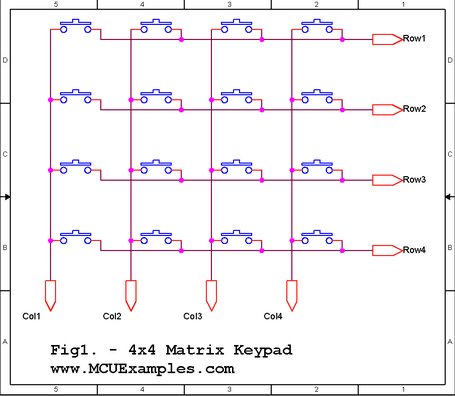
6. Repeat 5 for column 3 with respective modifications, (refer example code) and take row 3 key status in to keys variable bits 4:7. Now we have rows 1,2 and 3 data in keys bits 4:15
7. Repeat 5 for column 4 with respective modifications, (refer example code).
8. Now we have status of all 16 keys in variable keys and return that variable from ScanKeypad() routine
9. If we have at least one key pressed, then return from ScanKeypad() will be non zero.
10. If we get non zero value from ScanKeypad(), we should de-bounce keypad and identify really pressed keys and process them as required.
For more detail: Matrix Keypad interfacing with PIC microcontroller.
About The Author
Ibrar Ayyub
I am an experienced technical writer holding a Master's degree in computer science from BZU Multan, Pakistan University. With a background spanning various industries, particularly in home automation and engineering, I have honed my skills in crafting clear and concise content. Proficient in leveraging infographics and diagrams, I strive to simplify complex concepts for readers. My strength lies in thorough research and presenting information in a structured and logical format.
Follow Us:LinkedinTwitter