
Please check the update at === Digital Clock Updated Version ===
— Original Version —
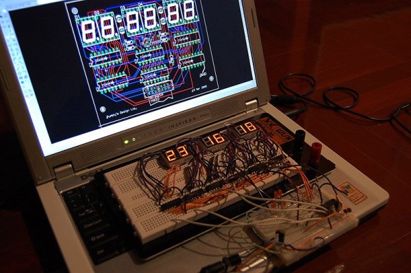
As I am a WIS so I built a clock as my first microcontroller project.
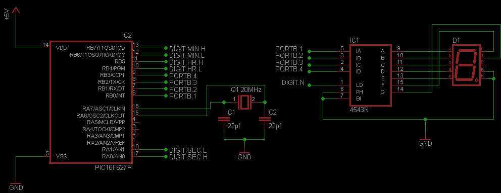
The clock is controlled by PIC16F628A from the PIC book . The idea was making a digital clock with hour, minute and second display. I just wanted to learn about microcontroller so the accuracy of the clock was not an issue (yet). However, I was trying to make it the most accurate as possible by using Timer1 Module of the PIC.
Timer1 Module (TMR1 Register)
The Timer1 Module is a 16 bit counter. It counts from 0x0000 to 0xFFFF and rolls over to 0x0000. The TMR1 interrupt is generated on overflow of the TMR1 register. More information about TMR1 is available in the data sheet of the PIC. In my clock, the PIC is running with 20MHz crystal so the internal clock is 5MHz. So, the duration between each TMR1 increment is 1/5000000 = 0.2 µs . That means TMR1 will overflow every 0.2 µs x 65536 = 0.0131072 s. If I count number of overflows to 77 times, I will get 1.0061744 s which is close to 1 second but the clock will gain about 6ms every second. The result will be a fast running clock (gaining about 9 min/day) .
To get a better accuracy, I make TMR1 counts to 62500 and set prescaler of the TMR1 to 1:8 (How these 62500 and 1:8 come? I did guess and test) . From these settings, the TMR1 will overflow every 1/5000000 x 8 x 62500 = 0.1 s. Counting number of overflows to 10 will yield 1 second. Just perfect huh!
Making Timer1 counts to 62500
It's easy. Just make it starts counting at 65536-62500 = 3036 = 0x0BDC by setting: (MikroC compiler)
Setting TMR0 requires 2 clock cycles but I have no idea about how many cycles required for setting TMR1L. If 2 cycles were required for setting TMR1L, I should set TMR1L to 0xDC+2 = 0xDE so my clock will run more accurate. The frequency drift in the crystal is also a source of inaccuracy of the clock. The time drift from crystal can be calculated by using data from data sheet of the crystal. Normally, it says 20ppm (Part-Per-Million). That means the crystal will produce error about 20 s. in 1,000,000 s. or about 1.7 s./day.
For more detail: Making a Digital Clock using PIC16F628A
About The Author
Ibrar Ayyub
I am an experienced technical writer holding a Master's degree in computer science from BZU Multan, Pakistan University. With a background spanning various industries, particularly in home automation and engineering, I have honed my skills in crafting clear and concise content. Proficient in leveraging infographics and diagrams, I strive to simplify complex concepts for readers. My strength lies in thorough research and presenting information in a structured and logical format.
Follow Us:LinkedinTwitter