
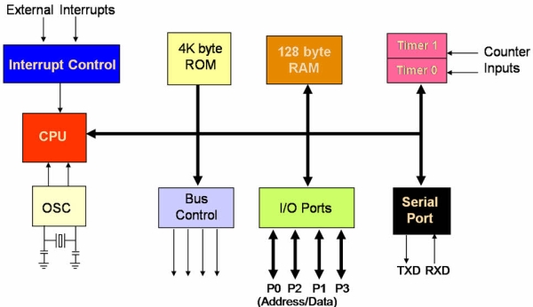
Interfacing is one of the important concepts in microcontroller 8051 because the microcontroller is a CPU that can perform some operation on a data and gives the output. However to perform the operation we need an input device to enter the data and in turn output device displays the results of the operation. Here we are using keyboard and LCD display as input and output devices along with the microcontroller.
Interfacing is the process of connecting devices together so that they can exchange the information and that proves to be easier to write the programs. There are different type of input and output devices as for our requirement such as LEDs, LCDs, 7segment, keypad, motors and other devices.
Here is given some important modules interfaced with microcontroller 8051.
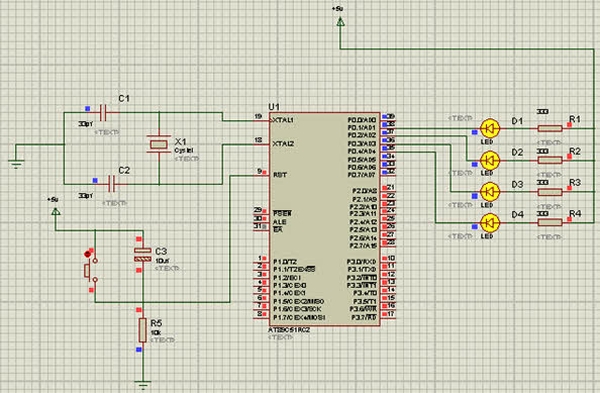
 1. LED Interfacing to Microcontroller:
Description:
LEDs are most commonly used in many applications for indicating the output. They find huge range of applications as indicators during test to check the validity of results at different stages. They are very cheap and easily available in a variety of shape, color and size.
The principle of operation of LEDs is very easy. A simple LEDs also servers as a basic display devices, it On and OFF state express meaning full information about a device. The common available LEDs have a 1.7v voltage drop that means when we apply above 1.7V, the diode conducts. The diode needs 10mA current to glow with full intensity.
The following circuit describes “how to glow the LEDs”.
LEDs can be interfaced to the microcontroller in either common anode or common cathode configuration. Here the LEDs are connected in common anode configuration because the common cathode configuration consumes more power.
Source code:
#include<reg51.h>
void main()
{
unsigned int i;
while(1)
{
P0=0x00;
for(i=0;i<30000;i++);
P0=0xff;
for(i=0;i<30000;i++);}}
2. 7-Segment Display interfacing circuit
Description:
A Seven segment display is the most basic electronic display. It consists of eight LEDs which are associated in a sequence manner so as to display digits from 0 to 9 when proper combinations of LEDs are switched on. A 7-segment display uses seven LEDs to display digits from 0 to 9 and the 8th LED is used for dot.
The 7-segment displays are used in a number of systems to display the numeric information. They can display one digit at a time. Thus the number of segments used depends on the number of digits to display. Here the digits 0 to 9 are displayed continuously at a predefined time delay.
The 7-segment displays are available in two configurations which are common anode and common cathode. Here common anode configuration is used because output current of the microcontroller is not sufficient enough to drive the LEDs. The 7-segment display works on negative logic, we have to provide logic 0 to the corresponding pin to make on LED glow.
Source Code:
#include<reg51.h>
sbit a= P3^0;
void main()
{
unsigned char n[10]= {0x40,0xF9,0x24,0x30,0x19,0x12,0x02,0xF8,0xE00,0x10};
unsigned int i,j;
a=1;
while(1)
{
for(i=0;i<10;i++)
{
P2=n[i];
for(j=0;j<60000;j++);
}
}
}
3. LCD Interfacing to Microcontroller
LCD stands for liquid crystal display which can display the characters per line. Here 16 by 2 LCD display can display 16 characters per line and there are 2 lines. In this LCD each character is displayed in 5*7 pixel matrix.
LCD is very important device which is used for almost all automated devices such as washing machines, an autonomous robot, power control systems and other devices. This is achieved by displaying their status on small display modules like 7-seven segment displays, multi segment LEDs etc. The reasons being, LCDs are reasonably priced, easily programmable and they have a no limitations of displaying special characters.
It consists of two registers such as command/instruction register and data register.
The command/instruction register stores the command instructions given to the LCD. A command is an instruction which is given to the LCD that perform a set of predefined tasks like initializing, clearing the screen, setting the cursor posing, controlling display etc.
The data register stores the data to be displayed on LCD. The data is an ASCII value of the characters to be displayed on the LCD.
Operation of LCD is controlled by two commands. When RS=0, R/W=1 it reads the data and when RS=1, R/W=0, it writes (print) the data.
Source code:
#include<reg51.h>
#define kam P0
sbit rs= P2^0;
sbit rw= P2^1;
sbit en= P2^2;
 void lcd_initi();
void lcd_dat(unsigned char );
void lcd_cmd (unsigned char );
void delay(unsigned int );
void display(unsigned char *s, unsigned char r);
void main()
{lcd_initi();
lcd_cmd(0x80);
delay(100);
display(“EDGEFX TECHLNGS”, 15);
lcd_cmd(0xc0);display(“KITS & SOLTIONS”,15);
while(1);}void display(unsigned char *s, unsigned char r)
{unsigned int w;
for(w=0;w<r;w++)
{lcd_dat(s[w]);}}
void lcd_initi(){lcd_cmd(0x01);delay(100);lcd_cmd(0x38);
delay(100);lcd_cmd(0x06);delay(100);
lcd_cmd(0x0c);delay(100);}
void lcd_dat(unsigned char dat)
{kam = dat;
rs=1;
rw=0;
en=1;
delay(100);
en=0;}void lcd_cmd(unsigned char cmd)
{kam=cmd;rs=0;rw=0;en=1;
delay(100);en=0;}
void delay( unsigned int n)
{unsigned int a;
for(a=0;a<n;a++);}
For more detail: Major Electronic Peripherals Interfacing to Microcontroller 8051
About The Author
Ibrar Ayyub
I am an experienced technical writer holding a Master's degree in computer science from BZU Multan, Pakistan University. With a background spanning various industries, particularly in home automation and engineering, I have honed my skills in crafting clear and concise content. Proficient in leveraging infographics and diagrams, I strive to simplify complex concepts for readers. My strength lies in thorough research and presenting information in a structured and logical format.
Follow Us:LinkedinTwitter