
Designing a simple and yet functional Line Follower Robot (LFR) is always a fascinating and challenging subject to be learned, the LFR actually could be implemented in many ways start from a simple two transistors to a sophisticated PID (Proportional, Integrate and Differential) which take advantage of the programmable feature of microcontroller to calculate the PID equation to successfully navigate the black track line on a white background surface. 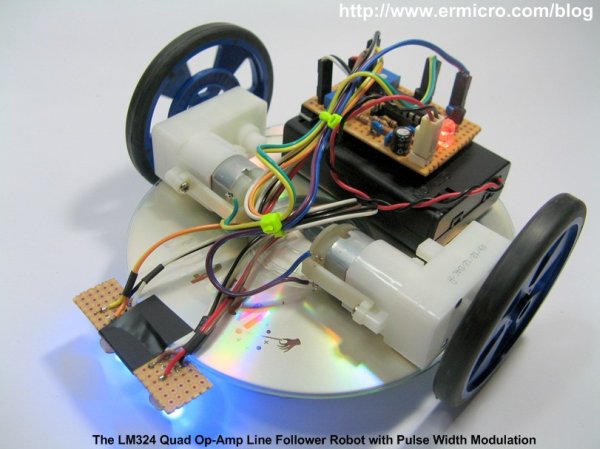
Designing a non microcontroller based LFR is quite challenging tasks as we need to limit the electronic components numbers so the LFR will not too complicated to be built by most average robotics beginners or electronic hobbyists, but at the same time we need to have a good speed control mechanism in order for the LFR to navigate the black track line successfully. The microcontroller based design LFR in the other hand is a popular choice because it reduces a number of electronic components significantly while still providing a flexible programmable control to the LFR.
On this tutorial we are going to build yet another LFR using just the standard analog components easily found on the market but use the same speed control method technique found in many good microcontroller based Line Follower Robot design. As the result we could get a good precision analog line follower robot that comparable to the microcontroller based Line Follower Robot design. On this tutorial you will also learn many useful information of how to use the operational amplifier.
The Line Follower Robot
This Line Follower Robot basically use a Cadmium Sulphide (CdS) photocell sensor or known as Light Dependent Resistor (LDR) and the high intensity blue Light Emitting Diode (LED) to illuminate the area under the photocell sensor to sense the black track line and the DC motor speed control technique to navigate the black line track as shown on this following picture:![]()
The easy method to navigate the black track line is to turn ON and OFF the left or the right DC motor according to the sensor reading (black turn OFF and white turn ON), but using this method will make the LFR to move in zigzag way. By proportionally control both left and right DC motor speed according to the light intensity level received by the photocell sensor (reflected back by the black track line) we could make the LFR easily navigate this track. The common technique to control the motor speed efficiently is to use a pulse signal known as the pulse width modulation or PWM for short.
For more detail: The LM324 Quad Op-Amp Line Follower Robot with Pulse Width Modulation
About The Author
Ibrar Ayyub
I am an experienced technical writer holding a Master's degree in computer science from BZU Multan, Pakistan University. With a background spanning various industries, particularly in home automation and engineering, I have honed my skills in crafting clear and concise content. Proficient in leveraging infographics and diagrams, I strive to simplify complex concepts for readers. My strength lies in thorough research and presenting information in a structured and logical format.
Follow Us:LinkedinTwitter