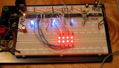
Things are moving along … With my new understanding of I2C master/slave communications, I’ve started work on larger arrays and finding the best way to manage the array and communicate the data to the host PC.
Above is the latest iteration of the project… and here is a lengthy description of what you’re seeing:
Along the top row you see six ICs, from left to right they are:
(hehe, I bet you’re thinking, I only see four ICs … well, there are six, trust me)
#1
Power Supply – 7805 – This is a regulated 5 volt power supply, with some filter caps, buffering caps and a power-on led. The 7805 is infact an integerated circuit, just disguised as a transistor.
#2
“SlaveA” – PIC16F876A – This is one of my slave microcontrollers … it autonomously scans its row (the bottom row) in the array with blistering speed, approx 500 uSec per pixel in the array, so 2 mSec total – which is kind of slow actually, as I add more lights to the array, the responsiveness of the array grows … I can probably shorten my sample time now. The blue LED indicates the slave is operational and the program is running.
#3
“SlaveB” – PIC16F876A – This is the second slave microcontroller, which scans the top row of leds. It is running the same program as SlaveA, but with a different slave address.
#4
“Master” – PIC18F252 – This is the third microcontroller, playing the master roll. It polls the slaves every 100msec for an update, and feeds that data to the host PC. This microcontroller is severe overkill for the job its doing, but these are the PICs i had on hand, so thats how the chips fell (har har har). The blue led indicates the master is polling a slave (in real-time, the led blinks very fast)
#5
“Clock” – DS1065T-060 – This is a digital clock generator from Dallas. It is programmed to generate any clock frequency I want, currently provideing a 20mHz clock that is used by all three pics. Although not as accurate as a crystal, it does provide better temperature stability … the only reason I am using it is to save board space (and the fact I obtained a sample of one from Maxim a long time ago but never used it) … three separate crystals and their associated load capacitors would have taken up way too much board space. The DS1065 is the first TO-92 package (on the left). Next to it is a regular 2n2222 transistor which controls the MCLR (reset) line on the slaves)
#6
“Interface” – MAX233 – This is a Maxim RS232 line driver IC … The MAX233 is very similar to the popular MAX232 except it requires no external capacitors for its voltage doubler circuit, again to save board space. This chip boosts the cmos level serial data from the “master” pic to TTL level for transmission to the host pc.
Operation of the slaves:
Each slave normally runs in a infinite loop, sampling the LED sensors as fast as it can and storing their values in a memory buffer. When a polling request is received from the master, an interrupt is generated which branches out of the sampling loop. I2C commands are pretty complex on paper, but merely a matter of setting and clearing bits in the digital world, so at 20mHz the pic handles them with lightning speed. Here is the blow by blow of the most complex series of commands, a multi-byte read
1) Master sets a “start condition” which basicly places a certain state on the bus
2) Master sends the slave address onto the bus with the read flag cleared… a slave address is the seven most significant bits of a byte (7:1), with the least signifcant bit (0) reserved for a read flag.
3) The I2C hardware in the slaves simultaniously receive this address, and compare it to their internally programmed addresses. The slave matching the address then sends an acknowledge bit on the bus.
4) Master receives the acknowledge bit and sends a command byte. Since the start condition is still present, the last slave addressed acknowledges receipt of the byte by sending an ack bit. This command byte is $04 in my application.
5) Slave receives the command, executes it and sends an acknowledge. The command $04 tells the slave to copy the ADC buffer to the transmit buffer.
5) Master receives the ack and sets a “restart condition”, which causes all the slaves to actively watch the bus for a slave address.
6) Master sends the slave address this time with the read flag set.
7) Slave matching the address sends an acknowledge. It then sends the first byte of the transmit buffer, without further prompting from the master.
8) Master receives the first data byte, and stores it in the receive buffer. The master sends an acknowledge.
9) The slave last addressed (since bus state is still START) sends the second byte in its transmit buffer.
10) Master receives the byte, stores it in its buffer, and sends an ack.
11) steps 9 and 10 repeat until the master sends an NACK and sets the bus state to STOP. This tells the slave to stop sending bytes.
each of these steps takes a tiny fraction of a second … the entire transaction is comprised of a multitude of commands and data going both ways and is finished in the blink of an eye, indicated by a fast flashing of the masters’ status led, which blinks twice (once for each slave), but the blinking repeats so fast, it looks as if the led is solid on.
If you’ve made it this far, congrats!
It is interesting to point out (not that I’ve seen any evidence of it on the host pc), that there is some lag introduced by the i2c routines in the ADC sampling process. Since i2c transactions are not just simple “one shot” commands, the slave is continuing to do ADC sampling while waiting for the next event from the master. This is acheived through the use of interrupts. whenever the slave is in the ADC loop, it gets pulled out to talk to the master, but since each time it talks to the master is only a very brief instant, its spending 99% of its time in the ADC loop. however, by me copying the ADC buffers to a transmit buffer only once during a transaction, the data in the buffer is ‘stale’ by the time it gets requested by the master. I’m going to look into ways of directly interfacing the i2c routines with the ADC buffers, which should let the master receive the freshest data possible. The problem here is, the ADC buffer is eight double-byte (word) values (only which four are actually used) but the transmit buffer is sixteen single-byte values, since the i2c protocol deals strictly with bytes. so the command to copy the adc buffer actually breaks the words into bytes to store in the transmit buffer. If I wanted to use the array to detect fast moving objects this would be important, but it responds to human interaction quite nicely now, even with the 100msec sampling delay imposed by visual basic. I think is due to the fact that the ‘missed’ samples are discarded instead of buffered, so the PC is still receiving real-time data from the array, just not very fast.
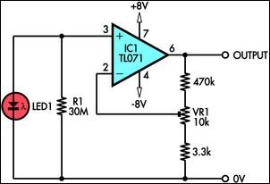
For more detail: LED Sensors


