
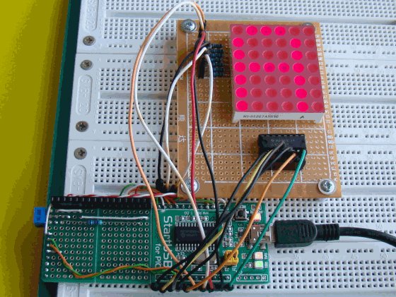
 In this experiment, we will discuss about the basic structure of a monochrome (single color) LED dot matrix and its interface with a microcontroller to display static characters and symbols. We will cover the animation stuff in next tutorial. I am using the PIC18F2550 microcontroller on the StartUSB for PIC board for demonstration, but this technique is applicable to any other microcontrollers that have sufficient I/O pins to drive the LED matrix. –
Theory of LED dot matrix display
In a dot matrix display, multiple LEDs are wired together in rows and columns. This is done to minimize the number of pins required to drive them. For example, a 8×8 matrix of LEDs (shown below) would need 64 I/O pins, one for each LED pixel. By wiring all the anodes together in rows (R1 through R8), and cathodes in columns (C1 through C8), the required number of I/O pins is reduced to 16. Each LED is addressed by its row and column number. In the figure below, if R4 is pulled high and C3 is pulled low, the LED in fourth row and third column will be turned on. Characters can be displayed by fast scanning of either rows or columns. This tutorial will discuss the method of column scanning.
The LED matrix used in this experiment is of size 5×7. We will learn how to display still characters in a standard 5×7 pixel format. The figure below shows which LEDs are to be turned on to display the English alphabet ‘A’. The 7 rows and 5 columns are controlled through the microcontroller pins. Now, lets see in detail how it works.
 Suppose, we want to display the alphabet A. We will first select the column C1 (which means C1 is pulled low in this case), and deselect other columns by blocking their ground paths (one way of doing that is by pulling C2 through C5 pins to logic high). Now, the first column is active, and you need to turn on the LEDs in the rows R2 through R7 of this column, which can be done by applying forward bias voltages to these rows. Next, select the column C2 (and deselect all other columns), and apply forward bias to R1 and R5, and so on. Therefore, by scanning across the column quickly (> 100 times per second), and turning on the respective LEDs in each row of that column, the persistence of vision comes in to play, and we perceive the display image as still.
For more deatil: Led Display Boards InBulk
About The Author
Ibrar Ayyub
I am an experienced technical writer holding a Master's degree in computer science from BZU Multan, Pakistan University. With a background spanning various industries, particularly in home automation and engineering, I have honed my skills in crafting clear and concise content. Proficient in leveraging infographics and diagrams, I strive to simplify complex concepts for readers. My strength lies in thorough research and presenting information in a structured and logical format.
LinkedinTwitter