Here I discuss very good knowledge based project LED blinking using timer0 of pic16f877 microcontroller. You can see in my Earlier project “Simple Project on LED blinking by PIC 16 Microcontroller” where I have used delay program for LED blinking. For LED blinking we have to call inbuilt/external delay program. Now think without calling delay program how LED blinking is possible?
It is possible and possible by using timer 0 of pic16f877 microcontroller. As we know pic16f877 microcontroller has three inbuilt timers. 1. Timer 0 2. Timer 1 3. Timer 2. For more knowledge on timer in pic16f877 please go through my old post “Timer Modules in pic16f877 microcontroller”.
Project Description
In this project, it is very easily discuss that how easily a LED is blinking using inbuilt timer of pic16f877 microcontroller with exact 1 sec time interval. Now think about the Timer0 register, which is TMR0 and how it work. We know TMR0 is 8-bit register so it takes time to count from 00h to FFh is 255×0.2µs=51µs (If we use 20 MHz crystal oscillator to run the microcontroller). In TMR0 when 255 count complete the overflow done and overflow flag is set. Now calculate how many overflow would we need, if we want to have an exact 1 second time delay? It would be over 19500 overflows. For 1ms delay would require about 20 overflows because we see for 1 overflow 51µs is needed. Now concentrate on prescaler value and how it affects counting of TMR0. Prescaler value of 1:4 would take 4 instruction cycles to increment TMR0 by 1. On the other hand, prescaler value of 1:256 requires 256 instruction cycles for the increment. With prescaler value of 1:256, one overflow would take 255x256x0.2µs=13056µs. Therefore, with 1:256, it would take only 76 overflows to have an exact 1 second timing.
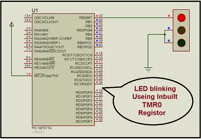
See the simple simulation circuit diagram of project “LED blinking using timer0 of pic16f877 microcontroller “
Now in c programming we have to concentrate on two spacial register operation_reg and INTCON. And we have to set proper bit pattern for both of this register as per our project need. For this project i set operation_reg = 87 H and INTCON= 00H. why i set operation_reg = 87 H and INTCON= 00H? For that please go through my post “Timer Modules in pic16f877 microcontroller”.
Now we can concentrate on Bit 2 position that is T0IF, of INTCON register because this bit is responsible for overflow occur in side TMR0. If TMR0 overflow occur it will set.
For more detail: LED blinking using timer0 of pic16f877 microcontroller
About The Author
Ibrar Ayyub
I am an experienced technical writer holding a Master's degree in computer science from BZU Multan, Pakistan University. With a background spanning various industries, particularly in home automation and engineering, I have honed my skills in crafting clear and concise content. Proficient in leveraging infographics and diagrams, I strive to simplify complex concepts for readers. My strength lies in thorough research and presenting information in a structured and logical format.
Follow Us:LinkedinTwitter