LED Binary Clock

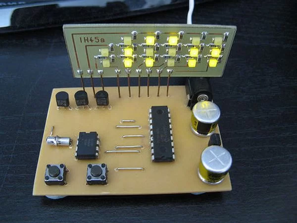
This second version is based around a PIC16F628A running at 4MHz to control the display, it also uses a DS1307 realtime clock chip to do the timekeeping. Every second the DS1307 sends a pulse to the PIC chip, the PIC then reads the internal time from the DS1307 over the I2C bus and then displays the time in binary on the LED display.
The bottom row of LEDs display the seconds, the middle rows shows the minutes and the top row is for hours. The time displayed in the picture is 01100:010011:011011 or in decimal 12:19:27. The time is in 24 hour format so goes up to 10111:111011:111011 or 23:59:59
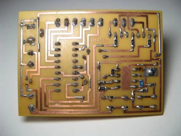
The PCB could be made double sided, or as I have done here single sided with 7 wire links soldered in place instead of the top copper layer. It has a 5 volt regulator so could be powered from any 9 – 15 volt DC power supply.
Step 1: Parts / Tools
As well as basic PCB making and soldering equipment you will need the following components:
1x PIC16F628A & programmer
1x DS1307 realtime clock chip
1x 32.768kHz watch crystal
3x BC548 (or similar) transistor
2x PTM pushbuttons
1x 78L05 regulator
2x 220uF electrolytic capacitors
17x Surface mount LEDs
1x DC power jack socket
5x 4.7K surface mount resistors
8x 100 ohm surface mount resistors
1x 2k surface mount resistor
12x zero ohm links (Or 11 zero ohm links and CR2016 backup battery)
1x 100nF surface mount capacitor
50cm single stranded bell wire
1x 9v – 15v DC power supply with DC jack
Step 2
Make PCBs & Program PIC
The first step is to make the PCBs, the PCB layout and schematics for the main clock and the display board are provided in Eagle format. The clock PCB is double sided, but the top layer consists simply of 7 links, this means that the PCB could also be made as a single layer with 7 wire links instead, this is the way I chose to make it as I cannot make double sided boards.
The display PCB uses exclusively surface mount devices while the main clock PCB uses a mixture of surface mount and through-hole components.
It is important to program the PIC chip with the hex file prior to soldering into the circuit as there are no ICSP connections on the board.
Step 3
Solder bottom components
Solder the 8 resistors, 1 capacitor and the zero ohm link / backup battery as shown to the bottom side of the main clock PCB.
Step 4
Solder top components
Next solder the through hole components ensuring to orientate the 2 chips, the 2 capacitors and the regulator correctly.
For more detail: LED Binary Clock using PIC16F628A microcontroller


