
Those days when I come home at night and strait into the darkness are finally over. This is a very practical device and I built it so that it is a module to my Dual Channel IR Remote Control. Because of that I ended up with a definite overkill of what is supposed to be a simple switch with a timer when I open/close my door. Anyway, it is modular+wireless and that’s what I like.
You can download the project files (including the ASM source code for the PIC) at the bottom of this page by clicking on red “download” button.
This add-on consists of a few key parts:
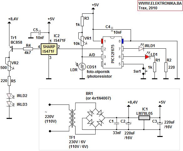
– Dual power supply with two outputs: 8.4V for IR LEDs and 5V for everything else
– Ambient light level measurement with CdS cell on A/D converter of PIC12F675 so that the lights don’t turn on during the daytime (for power saving feature – we must think green)
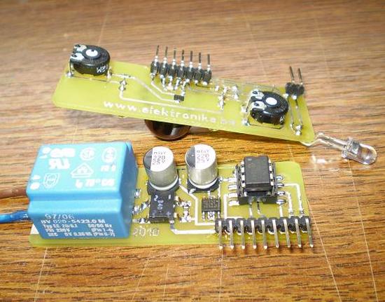
– Sharp IS471F obstacle detection sensor with two transmitting IR LEDs, plus an additional IR focus lens for longer range
– Third IR LED for RC5 code transmission for “remote controller” emulation by the PIC
How does it work
As I mentioned before, this is an add-on or a hack to my Dual Channel IR Remote Control (IR Remote Switch) project and after reading the description of that project it is clear that for it’s operation IR remote controller is required. No problem here since we can emulate RC5 remote controller with PIC and one IR LED. With this PIC we need to send IR codes for ON and SLEEP functions on every obstacle detection so that the IR Remote Switch turns the lights ON and sets them to SLEEP – meaning that they will turn off in about 1-2 minutes. That’s about all that this device does, besides measuring ambient light level and it also has a button to send 5 IR codes for programming the IR remote switch.
Setting up communication between these two IR devices
After putting this whole thing together make sure that the RC5 IR LED is pointed to the IR Remote Switch’s TSOP receiver. Next put IR Remote Switch to programming mode, and press the Sw1 button on this device. Now IR LED will start to send 5 IR RC5 codes that the IR Remote Switch will learn. Those codes are for channel A – ON and SLEEP.
Two pots to set
In the schematics you can see two potentiometers. One is for setting the range of IR obstacle detection (VR2) and the other one is for the ambient light level (VR1). You must set this light level pot so that the device thinks it is nighttime even if/when the lights in the hallway are ON. I was lucky with this because CdS cell can recognize this variation in light level. There is also a software threshold when switching from nighttime to daytime that is 4 minutes long. This is enough time to trigger the two RC5 code sending again when the door closes, even when the lights turn on after opening the door for the first time (the IS471F sensor sends the trigger signal twice every time, once the door opens and the other time when they close – mostly quickly after opening them).
Optics for obstacle detection sensor
Here we have two transmitting IR LEDs and IR focus/filter lens on the IS471F receiving sensor. This combination enables more range especially with the external more-powered supply for the IR LEDs.
For more detail: Leaving home light using PIC12F675 Microcontroller
About The Author
Ibrar Ayyub
I am an experienced technical writer holding a Master's degree in computer science from BZU Multan, Pakistan University. With a background spanning various industries, particularly in home automation and engineering, I have honed my skills in crafting clear and concise content. Proficient in leveraging infographics and diagrams, I strive to simplify complex concepts for readers. My strength lies in thorough research and presenting information in a structured and logical format.
Follow Us:LinkedinTwitter