Introduction
Electronics is my hobby. When I was in college I had some experience with microcontrollers; I did few projects with Atmel’s AT89C51. Recently, I have grown interest on PIC microcontrollers, and I thought I should start with 8-pin microchips. I picked PIC12F683 microchip. This microcontroller fascinated me a lot because I wanted to see what we can do with an 8-pin microcontroller (out of which 2 pins goes to power supply, so actually just 6-pins are left for I/O). So I thought of making my own learning board for this. In this project, I am first going to describe the learning board that I made, and then will demonstrate few experiments on it.
Some of the features of PIC12F683:
- Wide operating voltage range (2.0-5.5V)
- Precision internal oscillator (software selectable, 8 MHz to 125 Khz)
- 6 I/O pins with interrupt-on-change features.
- Four 10-bit A/D converters
- Two 8-bit and one 16-bit timers
- One Capture, Compare, PWM module
- In-Circuit Serial Programming
- Program Memory- 2048 words, SRAM- 128 bytes, EEPROM-256 bytes
 Circuit Layout and Design
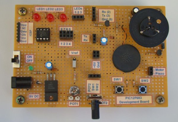
This learning board has the following features:
- A 9V DC input socket with power on switch
- Regulated +5V power supply using 7805 IC
- 3 output LEDs and 1 power on LED
- 2 input tact switches
- 2 potentiometers: one for analog input and the other for providing reference voltage for ADC
- Transistor-based TTL-RS232 level converter for serial communication.
- A DC motor with a transistor driver.
- A piezo-buzzer
Most of these features on the board are accessible through female header pins. None of the 6-I/O pins of PIC12F683 are hardwired to anything and they are accessible through header pins too. The figures below show PIC12F683 pins, the type of female headers and jumpers used to make connection on the board, and the detail circuit diagram of the learning board. Only the ISCP pins are accessible through male header pins. The entire circuit is built on a 8 x 12 cm general prototyping board.
As you see the output LEDs have 470Ω current limiting resistors in series so that a PIC pin can be safely drive them. The piezo buzzer is also driven directly by a PIC pin through a series resistor. The DC motor, however, is connected as a load to the collector of S8050 transistor as the required current to drive the motor cannot be supplied by the PIC port. So, the PIC port can switch on the transistor by pulling its base HIGH and the collector current of the transistor provides the sufficient current to drive the motor.
The TTL to RS232 level converter and vice-versa is achieved with two transistors and few other components. The negative voltage required for RS232 level is stolen from the RS232 port of a PC itself. Note that there is no hardware UART inside PIC12F683, so the serial data transfer from the microcontroller to PC will be possible only through a software UART through any of GP0, GP1, GP2, GP4, and GP5 ports (GP3 is input only). The transmitter and receiver port on microcontroller side are denoted by uTx and uRx, whereas on the PC side are denoted by Tx and Rx, respectively. The circuit diagram shows that the two input tact switches with the two potentiometer outputs and all the eight PIC12F683 pins are accessible through female headers.
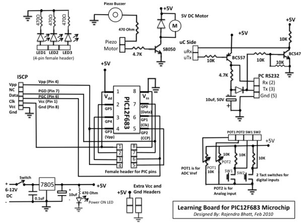 The tact switches are active low, i.e., under normal condition, a tact switch output is HIGH and when it is pressed, the output is LOW. There are couple of extra headers for Vcc and Gnd terminals which may be required while doing experiments. The power supply circuit is the standard circuit of 7805 regulator IC. A power-on LED is connected across Vcc and Gnd with a 470Ω series resistor.
The in-circuit serial programming (ICSP) of PIC12F683 can be done with two pins: ICSPDAT (pin 7), and ICSPCLK (pin 6). The programming voltage, Vpp, should be provided to pin 4 of PIC12F683 while programming. All the required ISCP pins are available through a male header, so the PIC can be programmed through any ICSP PIC programmer. Make sure that the sequence of ISCP pins on the programmer side and our learning board match.
For more detail: Learning Board for PIC12F683 Microchip
About The Author
Ibrar Ayyub
I am an experienced technical writer holding a Master's degree in computer science from BZU Multan, Pakistan University. With a background spanning various industries, particularly in home automation and engineering, I have honed my skills in crafting clear and concise content. Proficient in leveraging infographics and diagrams, I strive to simplify complex concepts for readers. My strength lies in thorough research and presenting information in a structured and logical format.
Follow Us:LinkedinTwitter