Introduction
The purpose of this final project is to implement a microcontroller-based platform stabilizer. The major components of the platform stabilizer is an Inertial Measurement Unit (IMU) and two 180 degree rotation servos. The IMU uses a combination of a 3-axis accelerometer and a 3-axis gyroscope to provide measurements of the platform’s motion and angular velocity. Readings from the IMU is communicated to the PIC via Inter-Integrated Circuit (I2C). The information of how fast the platform is accelerating in 3D space will be parsed by the PIC to determine which side needs to be corrected. The servos will apply equal and opposite force onto the platform to make real-time correction of the incline.
Our rationale for selecting the platform stabilizer is the various applications that exist, such as a camera stabilizer or a self-stabilizing serving tray. Movie and television productions currently use similar equipment to film, as it prevents the cameras from tilting or taking shaky videos. Additionally, this platform stabilizer would be perfect for waiters, because any tilt of the serving tray will be corrected automatically and eliminate the possibility of dropping dishes or spilling drinks. Our overall goal is to make a cost-effective product that can make users’ lives more convenient and less accident-prone.
High Level Design
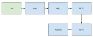
The high level design of the platform stabilizer is detailed in the flowchart below. As the user makes changes to the tilt or the angle of the base, readings from the IMU will change. This information is communicated to the PIC32, which in turn, will send the appropriate signal to one or both servos to oppose the tilt based on how much and how fast the incline is changing. The servos will then drive the platform in the opposite direction to keep it balanced.
Hardware
Appendix C includes a detailed schematic of our design for those wish to replicate it.
BNO055 Sensor:
This 9 DOF sensor utilized an accelerometer, gyroscope, and magnetometer in order to produce meaningful and accurate readings in either relative or absolute positions. Inside the sensor was a pre-programmed sensor fusion algorithm that quickly and accurately combined the data from the three separate sensors to provide values in quaternions, euler angles, and vectors. The types of data values that we had access to consisted of Absolute Orientation (Euler Vector, 100Hz), Absolute Orientation (Quaternion, 100Hz), Angular Velocity Vector (rad/s, 100Hz), Acceleration Vector (100Hz), Magnetic Field Strength Vector (20Hz), Linear Acceleration Vector (100Hz), Gravity Vector (100Hz) and Temperature (1Hz).
The sensor had far more functionalities than what we needed for this project. It not only provided separate acceleration and gyroscope values, but it also included fused sensor values, giving us euler angles and quaternions. This allowed for little drift and very accurate relative position angles. The values were stored in a large number of registers all defined in the datasheet. In order to read the values though, we had to write to the operation mode register and set it in the the mode that we wanted; in our case it was the IMU mode to get the euler angles.
We communicated with the BNO055 using I2C, which we found to be poorly documented and unreliable, so we will go into further detail in the Software section. In the hardware, the SCL and SDA pins of the sensor were connected to pins 17 and 18 respectively on the PIC32 according to the I2C setup. The PIC became the master and the sensor became the slave.
HS-422 Deluxe Servos:
We used two 180 degree rotation servos as our motors to correct the angle of the platform. Acceleration and orientation readings from the IMU were parsed and converted into signals that drove the servos to correct the platform in the direction opposite to which the user was tilting the base containing the IMU. The servos, which were powered with a 6V supply, were each optoisolated from the PIC32 (running at 3.3V) in order to protect their pins.
The servos required a Pulse Width Modulation (PWM) period of 20 ms (50 Hz) with a duty cycle between 0.55 ms and 2.45 ms, which we manually found. As described in the servo datasheets, a PWM of 1.5 ms centered the servos to 0 degrees. This was not always the case, as we saw when we discovered that one of them was off center by about 7 degrees. We compensated for this inaccuracy by manually tuning the centers of each servo.
Servo Brackets:
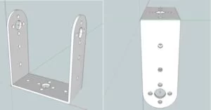
The servos brackets were attached to each servo and provided a flat surface to which another object could be attached. We stacked the first servo on top of the second servo bracket, and then attached the platform on top of the first servo’s bracket. The first servo was positioned to move the platform in the x-axis direction, while the the second servo was positioned 90 degrees relative to the first to move the platform in the y-axis direction.
The initial draft of the 3D model of these servo brackets were found online via 3D Warehouse, an open source library for Google Sketchup models. Modifications were then made to the model to shorten its width to better match the specific sizing of the servos we were using.
Because Sketchup did not support exporting SKP files into STL files (which are commonly accepted by 3D printing software), an STL plug-in was necessary to export the 3D model in STL format. Screen captures of the final CAD design of the brackets are illustrated in below.
Software
main.c
Next, we enabled output compares 1 and 2 in order to send duty cycles to our two servos in the other thread. We also set up pins 2 and 14 to be the outputs of OC1 and OC2 respectively, which were connected to servos 1 and 2. This allowed us to adjust each servo angle by sending out duty cycles through the output compare.
In addition, we set up the I2C bus to allow for communication between the PIC and the BNO055. To set it up, we called OpenI2C1(I2C_ON | I2C_SLW_DIS, 93). I2C was set up and modified using I2C1CONbits defined in the PIC32 datasheet. OpenI2C1 set the 15th and 9th bit to 1 and kept the rest at 0. The 15th bit, as the name shows, simply enabled I2C communication. The 9th, I2C_SLW_DIS, was used as a workaround from the I2C Errata as described in the datasheet. As it turned out, there were issues with the silicon used in the PIC32 which ended up causing problems in select things that should have worked but did not, including I2C. On page 10, it is described that “When I2C1 is enabled, all digital output-only functions and all analog functions on pin RA0 and RA1 do not function correctly”. The only workaround was to enable the DISSLW bit in the I2C1CON bits. The last argument, 93, set up the Baud Rate calculated by BRG = (Fpb / 2 / baudrate) – 2. We called configIMU to change the BNO005 mode of operation to IMU mode in order to get the euler angles of the relative position.
The rest of the code in main simply set up the threads and interrupts used by the timer.
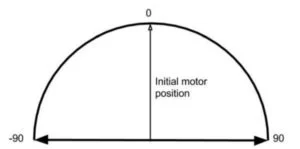
control thread: This thread displayed the euler angles onto the TFT and updated the duty cycle for the motor to reorient the platform horizontally. Initially, whenever the whole system was reset or turned on, this thread set the initial values of the IMU relative orientation with respect to the yaw, roll, and pitch angles. Ideally, on a completely flat surface, the roll and pitch angles would have been 0 degrees and the yaw could have been an arbitrary number since we had never used it as a servo variable. The initPitch, initRoll, and initYaw variables were set by reading consecutive registers from the IMU to produce a 16-bit signed value of the degree. A flag was set to 0 to ensure that this process was only completed once.
Otherwise, the variables eulerPitch, eulerRoll, and eulerYaw were updated by reading consecutive registers on the IMU. Since we had the initial values of all three angles set before, we could compare how much the pitch and roll angles had changed, so we set those differences to pitchDiff, yawDiff, and rollDiff. In each of the cases where we had to update eulerXX and initXX, we had to divide the values by 16 to adjust for the units used. In the case of the euler angles for BNO055, the degree values were measured with a sensitivity 16 LSB per unit, meaning that for every degree measured by the IMU, the register values actually read values that were 16 times the expected. This meant that we had to divide the registers by 16.0 in order to get the scaled desired values.
After the differences in roll and pitch were found, the motors were rotated to the negative differences to counteract the changing errors. These proportional corrections allowed for relatively quick reactions from the motors and brought the motors back to the initial calibrated state of 0 and 7 degrees. In addition, before the motors were rotated, the code checked to see if the current and previous differences were the same, meaning the imu had not been shifted or moved in any way and thus the motors did not have to be updated. This was added in to fix the oscillations we saw in the motors whenever they were trying to stabilize after correcting an error.
Other than the calculations and motor controls, the TFT displayed the initial euler angles, the current euler angles, and the current differences between initial and current angles. This helped in debugging and allowed us to see if the motors were updating correctly.
motor thread: This thread was used for testing and orienting the motors and was not included in the final code. We found that the motors themselves did not have a set value for 0 degrees and were thus often crooked whenever we tried to stabilize the platform. In order for the platform to remain horizontal, we had to manually tune the motors by adding 7 degrees to the output degree value for the second motor that controlled the Roll Angle adjustment.
servo.c:
I2C in main.c and i2cIMU.h:
To help explain the function definitions below, we will briefly explain how I2C device addressing, read and write are defined in the software:
In I2C, data is transferred through SDA in 8-bit sequences beginning with the MSB. During that time, the SCL line is brought high then low. The first 7 bits from the MSB are usually the register or device address, while the LSB is the read or write bit; read sets this LSB of the SDA to 1 and write sets it to 0. The slave then sends back an ACK to the master to signal that it has received the data if it is being written to. If it not being read, the master sends an ACK or NACK to indicate whether it wants to read consecutive registers or stop the transmission.
I2C Write: I2C read requires the I2C sequence to be initialized and the device address to be written to with the R/W bit set to 0. The programmer must then send the address of the register he wishes to write to as well as the data byte he wishes to write. Once the data byte is done transmitting, a stop sequence can be sent to finish the write.
I2C Read: To read from the device, the programmer must essentially perform an I2C write with the register he wants to read from and resend the start sequence to start the read process. He must then write the device address with the R/W bit set to 1 and start reading from the register he wants. For consecutive reads, an ACK from the master must be sent to the slave to read the next register. To only read one, a NACK must be sent to the slave and stop the sequence.
The I2C methods defined in main.c consisted of the following:
i2c1Read: This method was a general I2C read method with one argument called addr which was the desired address to be read from.
i2c1ConsecutiveRead: This method was a general I2C consecutive read method that read from two registers since the angle values were 2 bytes each. This allowed for fewer calls to read and better aligned register reads in the off chance that different values were being read from the desired registers. This could have resulted whenever read was being called multiple times. Thus, this method took in two arguments, startReg and num, with the first being the first register that would be read and the second being the number of registers the programmer wanted to read after the starting one.
Some general things we tried but did not work:
Mechanics
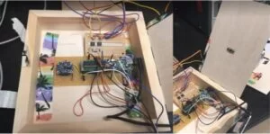
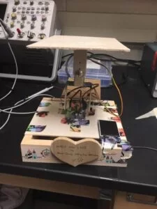
Next, we hot glued one of the servos to the center of the top of the other servo’s bracket. We then used duct tape to add some more stability to this area. Afterwards, we placed our soldered boards with the PIC32, IMU, and two optoisolators into an open box. We planned to cover the top with a piece of wood that we had sawed in half, above which the motors would sit. However, due to the fact that the bottom of the servo that we had planned to place on top of this piece of wood was not completely flat, we had to drill a few holes into the wood so that we could stick the protruding parts of the motor through it. We then hot glued the base of the bottom motor to the center of this rectangular piece of wood.
Finally, we attached this wood to the top of the box, making sure to leave space on two sides of the box to allow room for the wires to the servos, 6V power source, LCD, and USB cable for the PIC32 to connect to the boards. Ideally, we would have made the platform portable by using batteries instead of the 6V power source and the USB cable to power our motors and PIC. We also could have taken out the LCD, which we had used solely as a debugging method. However, for demo purposes, we did not do either. Below is an image of the inside of our box as well as the hole in the piece of wood we made for the servo.
Results of Design
As discussed above in the Software section, we discovered that the motors did not have a set value for 0 degrees and were often crooked whenever we tried to stabilize the platform. After several rounds of trial and error, we were able to calibrate our platform by sight so that when it was set down on a horizontal surface, it was as close to 0 degrees as we could get it to be. Thus, we manually tuned the motors by adding 7 degrees to the output degree value for the second motor.
Once we had everything properly calibrated, we were able to test the speed of execution and the bandwidth of our platform stabilizer by placing a water bottle on top of it and moving the base in a sinusoidal motion. We recorded the fastest speed at which we could perform this task without the water bottle falling off by roughly timing ourselves, and discovered that the bandwidth was about 0.5 Hz for both back and forth and right to left motions.
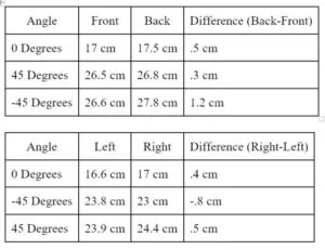
With the platform oriented so that the wooden heart was facing the front, we measured the differences in the heights of each end of the platform when the base was held at different angles. Whenever we moved the base to measure the heights at varying angles, we waited until the platform had stabilized completely before taking any measurements. This data allowed us to quantitatively display the accuracy of our platform stabilizer. A table of this data can be found below.
There was a concern involving the possible interference of temperature in our IMU readings and thus our platform. However, even when we were performing these tests in a warmer environment filled with students, we did not discover any noticeable differences in our data. Other than the temperature concern, we did not have to worry about any interference from other students’ designs.
In general, our project has a strong potential to aid waiters and anyone who wishes to take stable videos, such as television or movie producers. While we were able to successfully create an accurate product, its rate of adjustment to changes in angles was ultimately quite small. Thus, we would have to first make improvements to the stabilizing platform to increase support and bandwidth before it can be considered usable.
Conclusion
Improvements
Overall, we were pleased with the final outcome of our platform stabilizer. Because we were on a budget, we did not expect the platform to be incredibly stable. If we were to make improvements to the product in the future, we would shorten the height of the brackets and made them thicker. While this may reduce the torque, or range of motion of the servos, it would also increase the general stability. Additionally, we would spend more money on better and stronger servos to create smoother movements and adjustments to angles.We would also consider attaching the IMU directly to the platform rather than inside the base. Technically, in our current design, the IMU is adjusting the platform by using the position of the base and assuming that it is exactly parallel to the platform. However, in reality, the platform is not always perfectly parallel to the base. Due to the fact that we wish to keep the platform, not the base at 0 degrees, by making this IMU location change, we would be able to increase the accuracy of the design. Finally, we would attempt to work with PID rather than just using proportional mathematics to adjust the servos. The use of PID would result in more precise calculations.
Intellectual Property Considerations
We did not use anyone else’s design for this project. Code in the public domain that was used in this project were included the Protothreads Library. All other code was written entirely by us. We did not have to sign any non-disclosure forms for any part of the project. However, there were a few existing patents relevant to projects that were similar to ours, including a handheld platform stabilizing system that used distributed rotation sensors (US 20070050139 A1), as well as a camera stabilizer platform for a camcorder (US 20040223081 A1). Thus, because there were already so many products out in the market that were so similar to ours, we believe that there is minimal, if any, patent or publishing opportunity for our project.
Ethical Considerations
By the standards of IEEE Code of Ethics, we made an obligation to prioritize the safety of users when dealing with both the electrical and mechanical components of our project. We made sure to keep all the soldered connections inside the base to prevent any interaction with the electronics. By minimizing the number of exposed wires, we effectively reduced the chance of minor injuries. The solder boards were taped down to the bottom of the base to prevent any electrical components from moving and potentially getting damaged Properly sized screws were used to connect the servos to their brackets. The edges of wooden components were smoothed out to prevent any splinter-related injuries.
ISO and ANSI standards were considered to ensure that our project was safe, reliable, and of decent quality for the general public. Although we did not prototype a product that would be marketed to consumers, we chose to focus on a quality management system and customer satisfaction considerations in designing the platform stabilizer. We aimed for a simple design so that anyone could easily understand its purpose and have little difficulty utilizing it, and maximized benefits in assisting tasks such as waiting tables or recording smooth videos.
About The Author
Muhammad Bilal
I am a highly skilled and motivated individual with a Master's degree in Computer Science. I have extensive experience in technical writing and a deep understanding of SEO practices.