This is my first instructable…. ever. So here it goes.
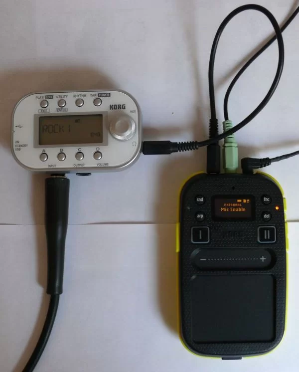
I own a Kaossilator 2 (KO2). It’s fun little phrase synthesizer and simple looper. But it has this awkward issue with mic button. When you want to record something from microphone you have to hold down two buttons simultaneously. First the mic button to enable built-in microphone or external input (mic in) and second the loop recording bank button. This isn’t an issue until you want to connect another instrument to it and record a loop. While holding down two buttons you have only one hand free to express your self as best as you can.
Imagine that mic enable button is toggle switch. You could enable external input and hold down bank button with your foot and have both hands free. We are now one step closer to our goal. But you still need to put KO2 on the floor, record a loop and then pick it back up. This calls for an foot switch which I’ll be making in my second instructable.
Since Korg is reluctant to incorporate mic input toggle functionality in software update this could be solved with a little hardware hack. There are many ways to latch a push button. It can be done with transistor circuit, logic gates, NE555 timer or an microcontroller (MCU) and probably some other ways too. My favorite is MCU since it uses least amount of components and can be soldered directly on KO2s PCB.
Step 1: Look inside
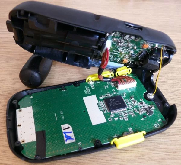
We see a nicely exposed signal line from SW7 to some resistors. This is a signal path of our mic button. Since there are no other components in the way we can just break the line and solder our MCU directly on the board.
Next thing to consider is that big black chip. Finding out functionality of its pins is important for tracing out the circuit. In our case the only pin that concerns us is Vdd 3.3V power line for our MCU.
Link to CY8C3244AXI-153 PSoC: http://www.cypress.com/?mpn=CY8C3244AXI-153
In datasheet we see that closest Vdd pins to our line are 26 and 100. And GND is everywhere. Entire mesh is GND.
So now we know where all of the signals that concern us are located.
Step 2: Choosing and programming MCU
MCU should be low pin count cause we only need two I/O pins. PIC10F series would be perfect for the job but they are not supported in mikroC PRO for PIC so I used the second best thing PIC12F series. I have few PIC12F675 chips lying around so I’ve used those. One in DIP package for breadboard and testing and one in SOIC package for soldering in KO2.
You could also use Atmel products: ATtiny13, 25, 45, 85.
Or Texas Instruments products: MSP430G2210, MSP430G2230
The cheapest and best way to go is with Texas Instruments MSP430 LaunchPad flash programmer and debugger. 10$ and free shipping worldwide!
Attached source code has been modified since I took pictures of soldering so 3.3V for pullup resistor is no longer connected to GP0 I/O pin. With this new code you should connect pullup resistor directly between Vdd and GP1.
IDE I used: Mikroelektronika: mikroC PRO for PIC 5.4
MCU: PIC12F675
In project settings disable reset pin and set clock source as internal clock.
Project settings: Shift+Ctrl+E
Build project: Ctrl+F9
Lastly just flash your SOIC MCU. For flashing I used PICkit 2 programmer. Girls, you should too =P
Step 3: Preparing MCU
I’ve cut off unused pins so they don’t touch the PCB but not completely so I can make software updates in the future. Note that pullup resistor should now be connected to the upper left 3.3V pin instead of pin 7.
Step 4: Preparing PCB and soldering
First off put MCU on PCB and mark where pins touch the PCB traces and scrape off green solder mask to expose copper.
Then break the mic button signal path between the exposed copper pads.
Apply solder to the exposed copper pads. Applying solder is much easier if you use some flux.
Now all we need is power supply. If we trace from pin 26 we get to capacitor C8 and then to perfect soldering spot. Be sure to use insulated wire. Mine is from some inductor.
For more detail: Kaossilator 2 hack: hands free (part 1/2)
About The Author
Ibrar Ayyub
I am an experienced technical writer holding a Master's degree in computer science from BZU Multan, Pakistan University. With a background spanning various industries, particularly in home automation and engineering, I have honed my skills in crafting clear and concise content. Proficient in leveraging infographics and diagrams, I strive to simplify complex concepts for readers. My strength lies in thorough research and presenting information in a structured and logical format.
Follow Us:LinkedinTwitter