JDM2 based PIC Programmer
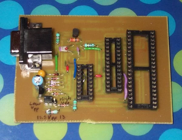
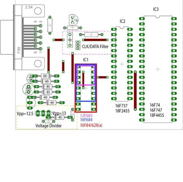
Schematic & layout for an updated JDM2 PIC Programmer. Includes clock & data filter, Vpp voltage divider for modern PIC microcontrollers (eg USB PIC 18F2455/4455).
Prior to reading sites like www.hackaday.com & www.makezine.com/blog I had worked only with the Amtel/AVR line of microcontrollers. After seeing all the cool projects people were doing with Microchip PICs, I HAD to have a PIC programmer. About a year ago I made my first PIC programmer based on the uJDM design (http://www.jdm.homepage.dk/newpic3.htm ). This programmer uses 6 common components. Though the link says ’16F84(a)’ only, I used it for the more modern (and cheaper) 16F628(a) processors without problems. This programmer has served me extremely well, but it is limited to (less than) 18 pin PICs with a programming Vpp of 13 volts.
This ‘instructable’ covers my new design that programs 8/14/18/28/40 pin PICs. The circuit is based on the JDM2 programmer (http://jdm.homepage.dk/newpic.htm ), with two enhancements: clock and data line filtering & selectable programming voltage.
The ZIP archive contains all the project files. The uJDM schematic and layout are included as well.
Design enhancements
Clock and Data Filter:
Newer PICs are programmed so fast that the clock and data lines can experience cross-talk. According to the author of WinPic programming software(http://www.qsl.net/dl4yhf/winpic/ ):
“There was a note on the Microchip forum (by Olin Lathrop) about programming the dsPIC30F201, suggesting to put 22..47 pF on the PGD and PGC lines to ground near the target chip. In addition, put a 100 ohm resistor in series with the PGD line between target chip and the cap. The resistor and cap on the PGD line low pass filter the PGD signal when it is driven by the target chip. This reduces the high frequencies that can couple onto the PGC line. The cap on the PGC line makes it less suceptible to coupled noise. We later found out that this important note also applies to the PIC18Fxxxx family. A user of a Velleman PIC programmer reported success with a PIC18F4520 after adding 2 * 33 pF caps and a 100 Ohm series resistor.” (LINK:http://www.qsl.net/dl4yhf/winpic/#pgd_pgc_filtering )
This note applies primarily to programming PICs through a cable while they are soldered into a circuit. When using this type of programming the extra capacitors and resistor must be near the target chip – it does not help to have them on the programmer:
“This means that this problem can not be solved at the programmer end of the cable. No amount of clever circuitry at the programmer can make this issue go away. It must be dealt with at the target circuit. (LINK: see PGD to PGC Crosstalk at http://www.embedinc.com/picprg/icsp.htm )
I emphasize this so it is clear you CANNOT slap a ICSP header on this board without issue. I included the filters in my new programmer because the data/clock traces are long. The capacitors are situated in the circuit so that they can be excluded without weakening the trace. The resistor can be replaced with a jumper wire.
For more detail: JDM2 based PIC Programmer


