
The 16×2 Alphanumeric LCD display is the most commonly used display among hobbyists and enthusiasts. The display is very useful when you want to display basic information to the user and can also help in testing or debugging our code. This particular 16×2 LCD module is easily available and has been popular for a long time. You can learn more about the basics of the 16×2 LCD module in the linked article.
To continue with our series of STM8 Microcontroller tutorials, in this tutorial, we will learn how to interface a LCD with STM8 Microcontroller. We have previously interfaced 16×2 LCD with many other microcontrollers as well, the tutorials are listed below and you can check them if interested.
- Interfacing LCD with ATmega16
- Interfacing LCD with Raspberry Pi
- Interfacing LCD with PIC Microcontroller
- Interfacing LCD with ARM7-LPC2148
- Interfacing LCD with NodeMCU
- Interfacing LCD with STM32
- Interfacing LCD with MSP430G2
If you are new to STM8, do check out the getting started with the STM8 Microcontroller article to understand the basics of the controller board and programming environment. We will not be covering the basics in this tutorial.
Working of 16×2 LCD Display
As the name suggests, a 16×2 LCD will have 16 Columns and 2 Rows. So in total, we will be able to display 32 characters on this display and these characters can be alphabets or numbers or even symbols. A simple 16×2 LCD pinout that we use in this tutorial is shown below-
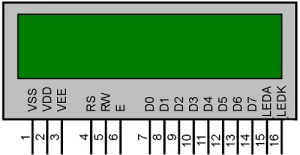
As you can see, the display has 16 pins and we can divide it into five categories, Power Pins, contrast pin, Control Pins, Data pins, and Backlight pins as shown in the table below. We will get into the details of each pin when we discuss the circuit diagram of this tutorial.
| Category | Pin NO. | Pin Name | Function |
| Power Pins | 1 | VSS | Ground Pin, connected to Ground |
| 2 | VDD or Vcc | Voltage Pin +5V | |
| Contrast Pin | 3 | V0 or VEE | Contrast Setting, connected to Vcc through a variable resistor. |
| Control Pins | 4 | RS | Register Select Pin, RS=0 Command mode, RS=1 Data mode |
| 5 | RW | Read/ Write pin, RW=0 Write mode, RW=1 Read mode | |
| 6 | E | Enable, a high to low pulse need to enable the LCD | |
| Data Pins | 7-14 | D0-D7 | Data Pins, Stores the Data to be displayed on LCD or the command instructions |
| Backlight Pins | 15 | LED+ or A | To power the Backlight +5V |
| 16 | LED- or K | Backlight Ground |
On the backside of the LCD, as shown in the image below, you will find two black dots, inside which we have the HD44780 LCD driver IC (encircled in red). Our microcontroller should communicate with this IC which in turn will control what is being displayed on the LCD. If you are curious to know how exactly all this works you should check out the working of 16×2 LCD display where we have already discussed how the LCD works in detail.
In this tutorial, we will discuss the circuit diagram and code to display alphamerical characters (alphabets and numbers) on a 16×2 LCD display using simple LCD_print_char and LCD_print_string commands. These commands can directly be used in the program after including our header file. The header file deals with all most of the stuff for you so it is not mandatory to know how the display or the HD44780 driver IC works.
Circuit Diagram to Interface LCD with STM8 Microcontroller
The complete STM8 LCD Circuit can be found in the below image. As you can see the connection for STM8S103F3P6 Controller with LCD is very simple, we have the LCD display directly connected to our board and the ST-link is also connected to program the board.
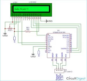
The power pins Vss and Vcc are connected to the 5V pin on the STM8S board, note that the operating voltage of LCD is 5V and is connected to operate on 3.3V. So even though the STM8S103F3P6 Microcontroller operates on 3.3V is mandatory to have a 5V supply for the LCD, you can avoid this by using a charge controller IC but we won’t be discussing that in this tutorial.
Next, we have the contrast pin which is used to set the contrast of the LCD, we have connected it to the potentiometer so that we can control the contrast. We have used a 10k pot, but you can also use other nearby values, the pot acts as a potential divider to provide 0-5 V to the contrast pin, typically you can also use a resistor directly to provide around 2.2V for reasonable contrast value. Then we have the reset (RS), Read/Write (RW), and Enable (E) pins. The read-write pin is grounded because we won’t be reading anything from the LCD we will only perform write operations. The other two control pins Rs and E are connected to PA1 and PA2 pins respectively.
Then we have the data pins DB0 to DB7. The 16×2 LCD can operate in two modes, one is an 8-bit operation mode where we have to use all the 8 data pins (DB0-DB7) on the LCD and the other is the 4-bit operation mode where we only need 4 data pins (DB4-DB7). The 4-bit mode is commonly used because it requires less GPIO pins from the controller, so we have also used 4-bit mode in this tutorial and have connected only pins DB4, DB5, DB6, and DB7 to pins PD1, PD2, PD3, and PD4 respectively.
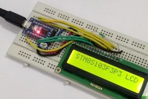
The last two pins BLA and BLK are used to power the internal backlight LED, we have used a 560-ohm resistor as a current limiting resistor. The ST-Link programmer is connected as always like in our previous tutorial. I made the complete connection on the breadboard and my set-up looks like this shown in the image below.
Source: Interfacing 16×2 Alphanumeric LCD display with STM8 Microcontroller
About The Author
Muhammad Bilal
I am a highly skilled and motivated individual with a Master's degree in Computer Science. I have extensive experience in technical writing and a deep understanding of SEO practices.