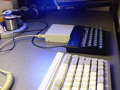
While I was writing some tips to solve problems about Spectrum’ keyboard, some guys asked me for the possibility of using a PC-keyboard coupled by adapter. One market solution was launched by ‘Sintech’, but isn’t available the scheme nor the program used by inner microcontroler. This lack of information pushed me to do an innovating project: I would do the design, prototype, programming, debugging, etc.
This adapter, developed for me has the name IMAR-3 and his article give all information to be constructed by electronic amateurs.
PC-Keyboard adapter for Spectrum
What this adapter do? Do I need to load something in my Spectrum?
This adapter is connected to expansion bus same as joysticks adapters, giving us the possibility of connecting an standard keyboard, type AT or PS/2. (Old keyboards 94-keys are unuseful). This heart of the adapter is a microcontroller PIC 16F84. This PIC should be programmed before insertion on the board ( a few steps forward will be explained how to program it). Once the PIC be programmed an inserted, is ready for working, and you don’t need to open nor load anything in your Spectrum. .
How this adapter works?
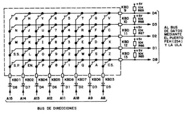
If you opened your Spectrum sometime, you found two flat cables, 8 and 5 contacts which are part of bottom of keyboard, a matrix under rubber keys. The matrix is divided in 8 half-rows with 5 keys each. The following figure shows this:
As you can see in the figure, every half-row is connected to one line in the upper-half of ADDRESS BUS, and the other end of every key is tied in a five-group to a line of DATA BUS, D0 to D4, through the ULA. When a key is pressed, the whole half-row is read (5 keys) and the I/O port writes a ‘0’ in the address line of this half-row. For clarify: Let’s assume that we want to know if is press the key ‘W’. Then we read the port IN (64510)binary is 11111011 11111110. This reading set to ‘0’ the line A0, telling to ULA that the keyboard is being read, and also the line A10 is set to ‘0’, meaning that half-row number 2 is being read. In response, a number will be set, which binary bits are tied ,from D0 to D4 with keys ‘QWERT’ one to one, because DATA BUS is forced to ‘1’ throu resistors R65-R69. (one key released means ‘1’ and if pressed, is set to ‘0’, got from address bus).
In this example, is the bit D1 which shows the status of key ‘W’. You can see this ‘online’ writing following program and see the changing status depending the key you press in the half-row ‘QWERT’. If the value is set to binary, is more clear to understand. In a emulator works fine, indeed!.
For more Detail: IMAR-3 PC-KEYBOARD ADAPTER FOR SPECTRUM pic16f84


