
This document describes how to generate composite color video signals in software using an SX microcontroller. First the document describes the video signal and after that how to do it in software.
There is also a zippped PDF-version (1.54MB) of this document, that is better if you wnat to print it to paper. (Note: The PDF-file also contains the games pong and tetris with source, so you might not want to print the whole document, also note that the document is supposed to be printed on both sides of the paper making some of the even pages are empty)
Index
Background
The composite video signal
How to do it in software
Emulators
Conclusions
Links
Questions ?
Copyright Note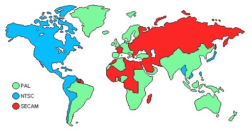
Background
Back in early 1998 I made some experimenting using a PIC16F84 microcontroller (3MIPS of processor power) to generate composite B&W video signals on the fly in software, with two resistors as the only video hardware. I made the two classical games Pong and Tetris with this technique and published them including source on my homepage. Since then it has been built by several hundreds of people. During the Christmas 1998-1999 I got some equipment from Scenix (nowadays known as Ubicom) and made some experiments to generate color video signals using an SX chip, but before I got any results my programmer broke down, at least that was what I believed, and I stopped developing it. In the early summer of 2001 I was told by people at Parallax that it was the early versions of the SX-chips that had a bug in them so my programmer was just fine, so they gave me some new chips and I continued my work. After some new experiments, calculating and many late hours and a bit of luck I got my TV to lock onto the color signal an d by the end of summer I got a Tetris game up and running. During the fall I developed the Pong game, which was finished during the Christmas holidays 2001-2002. I didn’t release the games as there were some details left to take care of. I didn’t want to publish them until they were as perfect as possible due to my bad experience with my PIC-based games that were spread in early bad versions. Now in spring 2003 I decided that I shouldn’t do any more improvements of the games as I don’t have time to work on them and I got to stop sometime. The biggest remaining issue is that it only works good for NTSC, it is much harder to get a correct PAL signal in software, but that is a problem for someone else to solve. Another issue about the games was this text about generating color video signals that I wanted to finish before I released the games, to not get that many questions about video generation that I don’t have time to answer. After reading this document you will hopefully understand how to generate color composite video signals in software. To fully understand this you need mathematical knowledge at university level, some RF-knowledge would also help a lot.
The composite video signal
To understand anything about generating video signals in real-time, one must know how video-signals work in detail, so before we look at any code we’ll have to talk about video signals.
How a standard TV-set works
A standard TV-set is built with a vacuum tube, which has a phosphor screen that an electron canon shoots at. When the electrons from the cannon hits the screen, light is emitted from the phosphor when the canon shoots electrons at it, and it also has a short afterglow making each pixel lit until the electron beam hits it again. The electron beam from the electron-cannon can be bent using magnets so it shoots at different parts of the screen. If this is controlled so it draws horizontal lines all over the screen repeatedly, while the intensity of the beam is modulated, an image can be drawn on the screen. The screen is redrawn 25 times per second (on a PAL system), but to reduce flickering the image is interlaced, showing first all odd lines then all even lines, so the image is partially updated 50 times per second. Thanks to the “persistance of vision effect” of the human brain the image seems to be constant instead of flickering at 50Hz.To get color each dot on the screen is divided into three colors: red, green and blue.
Different TV standards
There are three major analog TV-standards: NTSC, SECAM and PAL as seen on the map above. The NTSC (Short for “National Television System Committee”, but back in the early days of TV there was problems with getting the same color over the whole picture so a more evil interpretation of the letters is that it stands for “Never The Same Color” ) is the American TV-standard, it has only 525 scan-lines, but it has a update frequency of 30Hz. SECAM (Short for “SÉquentiel Couleur Avec Mémoire” (French for “SÉquentiel Couleur Avec Mémoire” (French for “Sequential Color With Memory”), but as the French usually want to get their own solution to problems, a more evil interpretation is that it stands for “System Essentially Contrary to the American Method”) is the French TV-standard, it has improved color stability and higher intensity resolution but with less color resolution, I don’t know much about that standard. The European standard is PAL (Phase Alternating Lines, or as a PAL enthusiast would interpret the letters: “Perfect At Last”), it has 625 lines per frame, 25 frames per second. It is based on NTSC, but the color-coding has been improved by using a phase shift on every other line to remove the color errors that occurred with NTSC.
The information in the video signal
The image seen on the screen has different intensities. As the electron beam sweeps over the screen, the intensity that should be at the position of the beam, is sent as a voltage level in the video signal. There is no information in this intensity information about where the electron beam is on the screen. To solve this, a synchronization pulse is sent in the beginning of each line to tell the TV that the current line is finished and move down the electron beam to the next line. (Like the Enter key on the keyboard, when writing a text with a computer) The TV must also know when a new image is coming, this is done by making a special synchronization pattern. (Like the “new document” function when writing a text with a computer) An image that is updated 25 times per second would be quite flickering, so therefore all even lines are drawn first and then all odd, this method shows 50 half images per second, making the picture have less flickering. The information whether the image contains even or odd lines are sent in the vertical synchronization pattern, as different patterns for odd and even images. The video signal has a voltage range 0 to 1V, where 0.3V represents black, and 1.0V is white (gray intensities have voltages between these values). Levels close to zero represent synchronization pulses.
The scan-line
The image is divided into scan-lines, it is the most important part of the image since it contains the image data. The scan-lines are all 64us long. First a 4us long sync pulse is sent, by setting the signal level to 0V, to tell the TV that a new line is coming. The old TV’s was kind of slow, so they needed 8us after the sync-pulse to get the electron beam in position. During this time the signal is kept at black level. The 8us delay is followed by the image data for 52us, drawn on the screen from the left to the right with the intensities obtained from the video signal. Black is represented by 0.3V and as the voltage increases the intensity increases, with the maximum intensity at 1.0v (white). See the image right to see the scan-line. The color information is added as two amplitude modulated sinus waves, we’ll get back to that later.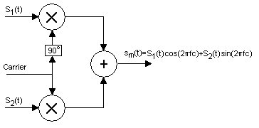
Putting the scan-lines together to an image
An image is built from 625scanlines, but a TV doesn’t show 625 lines. Some of the lines are used for synchronization pulses, and some lines are invisible (I don’t know exactly how many) because old TVs needed some time to move the electron beam from the bottom of the screen. (Those invisible lines are nowadays used for other purposes, Text-TV for example).
Vertical synchronization pulses.
To tell the TV that a new image is coming, a special pattern of synchronization pulses is sent. Since the picture is built from two half pictures, the pattern is different for the odd and even images. The vertical synchronization pulses looks like this:
This picture shows the different vertical synchronization pulses for the two half images. Outputting this pattern is what you need to send to the TV for the tv to do a “vertical sync”. The levels are 0v and 0.3v. Numbers below signals shows scan-line number. (Click to enlarge)
For more detail: Howto generate color video signals in software – Introduction
About The Author
Ibrar Ayyub
I am an experienced technical writer holding a Master's degree in computer science from BZU Multan, Pakistan University. With a background spanning various industries, particularly in home automation and engineering, I have honed my skills in crafting clear and concise content. Proficient in leveraging infographics and diagrams, I strive to simplify complex concepts for readers. My strength lies in thorough research and presenting information in a structured and logical format.
Follow Us:LinkedinTwitter