
For programming PIC microcontrollers we require a piece of hardware that can communicate between the computer and the microcontroller known as a programmer. There are several programmers available out there but we will be using PICkit3 for this example due to its versatility. One important note before we start, is that if you plan on buying a PICkit3 programmer/debugger, make sure you buy it from Microchip or Microchip authorized dealers only, otherwise there’s no guarantee that the programmer will work, in fact we had to buy a second PICkit3 because the first one we bought was a Chinese clone and didn’t work.
In order to learn how to burn programs into a PIC microcontroller, you need to understand the following topics:
-ICSP
-Hardware connections
-MPLAB X IDE and IPE
-Configuration Bits
So let’s get into these topics one by one.
In general, there are two methods for programming PIC devices.
Self-Programming
This technique uses a special program known as a Bootloader to write the code into the controller’s program memory via different interfaces such as UART, SPI etc. This technique is used when there are frequent firmware updates in the system. The disadvantage of this method is that an extra program space is used for the Bootloader.
In-Circuit System Programming(ICSP)
ICSP is a technique where a device is programmed even after the device is placed in a circuit board. This means that the pins used to program the microcontroller can also be used as a GPIO pin after programming is completed.
The pins used for programming are:
- MCLR/Vpp
- Vdd
- Gnd
- ICSPDAT
- ICSPCLK
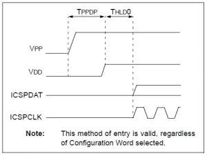
How does the microcontroller know that it is in programming mode?
The device enters the programming mode by applying a set of signals to the programming pins.
For example, for PIC16F88X the programming mode can be activated by holding ICSPDAT(PGD) and ICSPCLK(PGC) low while raising MCLR pin from VIL to VIHH (13V), then applying VDD and data. These actions are performed by PICkit3 in a synchronized manner.
Once in the programming mode, the IC knows whatever data comes next to programming pins are not I/O(input/output) signals, rather they are ICSP commands or data to be written into the FLASH memory.
But where does this data come from?
Well, this is where the MPLABX IDE comes into the picture. MPLAB X is a free software development tool used to write/edit, compile, debug and download your code onto a microcontroller.
Hardware connections
- Connect MCLR from PICkit3 to MCLR (Pin1) of IC and pull-up using a 4.7k resistor.
- Connect Vdd and Gnd from PICkit3 to Vdd (Pin32) and Gnd (Pin31) of IC.
- Connect ICSPDAT and ICSPCLK from PICkit3 to IC.
- Connect an LED through a 470ohm resistor on pin RA6 (Pin10).
- Apply 5V DC on Vdd and Gnd.
- Connect the PICkit3 to the computer using the USB cable.

- Pin 32, 11 and 31, 12 are internally shorted in the IC.
- ICSPDAT and ICSPCLK are sometimes also known as PGD and PGC.
Steps to create a new project
Open the IDE and create a new project by following the steps given below:
- Choose, project – Microchip embedded–>Standalone project
- Select device – Device–>PIC16F887
- Select tool – Hardware tools–>PICkit3
- Select compiler -Compiler Toolchains–>XC8 (Click ‘Download latest’ for the first-time install)
- Select project name –Type in a suitable name and click finish.
After creating a new project we need to add a source file.
Right click on source file–>new–>main.c and give it a name.
Now before writing our first code, let us understand the significance of ‘CONFIGURATION BITS’. These bits as the name suggests, are used to configure the microcontroller. These bits are used by MPLAB IPE and PICkit3 to take some important decisions such as, whether we’ll be using the Internal or an external oscillator, setting up the clock frequency, programming the pic microcontroller either in high voltage programming mode or low voltage programming mode etc.
To configure these bits:
Go to Window–>PIC Memory Views–>Configuration Bits
At the bottom select these options
FOSC EXTRC_CLKOUT HS (For crystal oscillator)
WDTE OFF
PWRTE OFF
MCLRE ON
CP OFF
CPD OFF
BOREN ON
IESO OFF
FCMEN OFF
LVP OFF
BOR4V BOR40
WRT OFF
Click Generate Source code. Copy the code generated at the bottom of the screen and paste into the main source code.
A simple LED blink program is given below.
/*
* File:   Blinky.c
* Author: Murtaza.S
*/
// CONFIG1
#pragma config FOSC = HS                   // Oscillator Selection bits (HS oscillator)
#pragma config WDTE = OFF               // Watchdog Timer Enable bit
#pragma config PWRTE = OFF             // Power-up Timer Enable bit
#pragma config MCLRE = ON              // RE3/MCLR pin function select bit
#pragma config CP = OFF                    // Code Protection bit
#pragma config CPD = OFF                 // Data Code Protection bit
#pragma config BOREN = ON             // Brown Out Reset Selection bits
#pragma config IESO = OFF               // Internal External Switchover bit
#pragma config FCMEN = OFF          // Fail-Safe Clock Monitor Enabled bit
#pragma config LVP = OFF                // Low Voltage Programming Enable bit
// CONFIG2
#pragma config BOR4V = BOR40V   // Brown-out Reset Selection bit
#pragma config WRT = OFF        // Flash Program Memory Self Write Enable bits
#include <xc.h>
void delay(unsigned int t);

void main(void){
TRISA = 0x00;
PORTA = 0x00;
while(1){
PORTA = 0xff;
delay(500);
PORTA = 0X00;
delay(500);
}
}
void delay(unsigned int t)     // This is a simple loop to generate delay.
{
unsigned int i,j;
for(i=0;i<t;i++)
{
for(j=0;j<120;j++);
}
}
Click on build main project (F11).ode>
Now open the MPLAB IPE
Select the device as PIC16F887, click apply, import the hex file by clicking on browse. The Hex file can be found in MPLABX PROJECTS–>project folder name–>dist–>default–>production.
Finally, click ‘program’ to burn the code into your device.
Source: How to Use PICKit3 to upload code to pic microcontroller
About The Author
Ibrar Ayyub
I am an experienced technical writer holding a Master's degree in computer science from BZU Multan, Pakistan University. With a background spanning various industries, particularly in home automation and engineering, I have honed my skills in crafting clear and concise content. Proficient in leveraging infographics and diagrams, I strive to simplify complex concepts for readers. My strength lies in thorough research and presenting information in a structured and logical format.
Follow Us:LinkedinTwitter