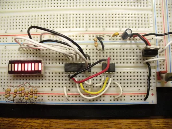
Intro:
How to use a 74HC595 Shift Register with a AVR ATtiny13
If you have been playing with microcontrollers and electronics then you have likely seen LED dot matrix displays and other projects that use shift registers like 7-segment displays and more. This instructable goes over a quick intro to the 74HC595 8-Bit Serail to Parallel Shift Register with Latch and how to interface it to an AVR ATtiny13 to flash some LEDs.
What you need:
1 – Breadboard
1 – Power Source – 7805 or some other 5v source
1 – ATtiny13 and a way to program it ( I’m using the AVRISP mkII with AVRStudio 4.17 w/ WinAVR)
1 – 74HC595 Shift Register
1 – 100uF cap
1 – 0.1uF cap
1 – 10K resistor
8 – LEDs
8 – 470ohm resistors
~15 – hookup wires
What is a Shift Register?
Serial to Parallel Shift Registers are ICs that allow “serial” data to be clocked in on 1 pin and stack up in a register which is output on 8 parallel pins (in the case of a 8-bit shift register). As data is clocked in, it shifts all the other bits over one position with the end one falling off. Common shift registers are 74HC164 and 74HC595.
There’s a couple of good online tutorials about these with animations.
www.eelab.usyd.edu.au/digital_tutorial/part2/register01.html
The 595 has another feature which is cool. It’s called a latch. It allows the outputs to show the current bits which have been latched in the Latch Register while new data is shifted into the Shift Register. Then toggle the latch pin and the new data is copied into the Latch Register.
Here’s a link to the 74HC595 Datasheet:
www.onsemi.com/pub_link/Collateral/MC74HC595A-D.PDF
Check Out a Youtube Video of the Circuit in Action
Step 1:
Get Familiar with the 595
The 74HC595 is a pretty cool little package. We are going to hook it up to shift in a pattern of leds
The pin out goes like this:
Pin 1 – Output B – source for LED (+)
Pin 2 – Output C – source for LED (+)
Pin 3 – Output D – source for LED (+)
Pin 4 – Output E – source for LED (+)
Pin 5 – Output F – source for LED (+)
Pin 6 – Output G – source for LED (+)
Pin 7 – Output H – source for LED (+)
For more detail: How to use a 74HC595 Shift Register with a AVR ATtiny13


