Any microcontroller based system typically has an input and a corresponding output. Taking simple output with a PIC microcontroller has been explained in LED blinking with PIC18F4550. This article explains how to provide an input to the controller and get a corresponding output using PIC18F4550.
PIC18F4550 has a total of 35 I/O (input-output) pins which are distributed among 5 Ports. Each Port of a PIC microcontroller corresponds to three 8-bit registers (TRIS, PORT & LAT) which should be configured to use the Port for general I/O purpose. For more details, refer LED blinking using PIC.
|
TRISD
|
Bit 7
|
Bit 6
|
Bit 5
|
Bit 4
|
Bit 3
|
Bit 2
|
Bit 1
|
Bit 0
|
|
Value
|
1
|
1
|
1
|
1
|
1
|
1
|
1
|
1
|

|
TRISD
|
Bit 7
|
Bit 6
|
Bit 5
|
Bit 4
|
Bit 3
|
Bit 2
|
Bit 1
|
Bit 0
|
|
Value
|
–
|
–
|
–
|
–
|
–
|
1
|
–
|
–
|
|
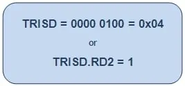
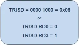
TRISD
|
Bit 7
|
Bit 6
|
Bit 5
|
Bit 4
|
Bit 3
|
Bit 2
|
Bit 1
|
Bit 0
|
|
Value
|
–
|
–
|
–
|
–
|
1
|
–
|
–
|
0
|
Project Source Code
###
// Program to control an LED using a switch
// Configuration bits
/* _CPUDIV_OSC1_PLL2_1L, // Divide clock by 2
_FOSC_HS_1H, // Select High Speed (HS) oscillator
_WDT_OFF_2H, // Watchdog Timer off
MCLRE_ON_3H // Master Clear on
*/
void main()
{
ADCON1=0x0F; // Set all pins as digital I/O
CMCON=0x07; // Set all comparators as digital I/O
TRISA.RA0=0; // Configure pin RA0 as output
TRISA.RA5=1; // Configure pin RA5 as input
while(1)
{
if(PORTA.RA5) // If input is high
LATA.LATA0=1; // Turn the LED On
else
LATA.LATA0=0; // Turn the LED Off
}
}
###
Project Components
Project Video
Source: How to take input with PIC18F4550 Microcontroller
About The Author
Muhammad Bilal
I am a highly skilled and motivated individual with a Master's degree in Computer Science. I have extensive experience in technical writing and a deep understanding of SEO practices.