How to interpret the direction of rotation from a digital rotary switch with a PIC
The objective for this Instructable is to illustrate how to interface a digital (quadrature coded) rotary switch with a microcontroller. Don’t worry, I’ll explain what quadrature coded means for us. This interface and the accompanying software will allow the microcontroller to recognize the direction of rotation for each move from one detent to another.
I recently used this type of switch in a microcontroller project that required a pressure set point to be entered using a knob with 16 detents instead of up/down buttons. The idea was to allow the user to “dial in” the desired pressure. As a result, we had to develop a software routine to get the position information from the switch and deduce the rotation direction in order to increment or decrement the pressure set point for the main system.
In this Instructable, I’ll cover the physical interface to the microcontroller, the theory of operation for the rotary switch, the theory of operation for the software as well as the deduction routine. Finally, I’ll show you my application of the deduction routine. As we progress, I’ll try to keep things somewhat generic so that the idea can be applied on as many platforms as possible but I’ll also share what I did so you can see a specific application.
Parts
In order to implement this, you’ll need:
A rotary switch (quadrature coded)
Pull up resistors
Suitable microcontroller platform
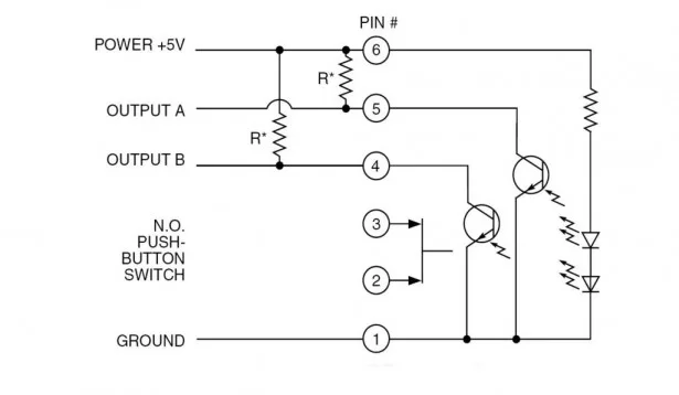
For my project, I used a Grayhill 61C22-01-04-02 optical encoder. The data sheet for the rotary switch calls for 8.2k ohm pull up resistors on the two data lines coming from the switch. You’ll want to check the data sheet for the encoder you opt to use. The rotary switch I used can also be ordered with an axial push button switch. It’s a useful feature for committing selections that have been dialed in, etc. but I will not be discussing its interface here. I have a ”suitable microcontroller platform” listed because (I think) this can be implemented on more than one platform. I have seen a lot of people using other microcontrollers for Instructables so I want to show the general approach as well. I wrote all the code in PIC Basic Pro for use with a Microchip PIC16F877A. Really, the key thing that you need on the microcontroller is the ability to interrupt when there is a logic change on either of two pins. On the PIC16F877A, this is called the PORTB change interrupt. There may be other names for it on other controllers. This microcontroller interrupt feature is part of what makes this implementation so elegant.
Hardware Interface
A ”simple” solution would be to have a ”single pole-16 throw” switch with 16 connections to the microcontroller. Each switch output would then be tied to a pin on the microcontroller so that every dial position can be checked by the microcontroller. This is an excessive use of I/O pins. Things get even worse if we want more than 16 positions (detents) available to us on the switch. Each extra position on the switch would require an extra input to the microcontroller. This quickly becomes a very inefficient use of inputs on a microcontroller.
Enter the beauty of the rotary switch.
The rotary switch has only two outputs to the microcontroller listed as A and B on the data sheet. There are only four possible logic levels that these lines can take: AB = 00, 01, 10 and 11. This greatly reduces the number of input lines you must use in connecting the switch to the microcontroller. So, we’ve cut the number of input lines down to just two. Now what? It seems like we really need 16 different states but this new switch has only four. Have we shot ourselves in the foot? Nope. Read on. We’ll cover a little bit of the theory behind the rotary switch operation to explain.


