Hello Friends, Welcome back. In the last tutorial we started working with MPLab and HI-TECH C Compiler and written our first C program to blink LED. After compiling the program we got the HEX file. Now, in this tutorial we will see how to transfer(burn) the hex file to our Microcontroller chip and then power it up to actually blink the LED.
We will use eXtreme Burner – PIC , which is a easy to use GUI programmer for PIC18 MCUs. The burner supports USB connectivity with PC so it is very easy to install and use.
Launch eXtreme Burner – PIC from Windows Desktop or Start Menu.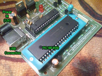
Fig.: eXtreme Burner – PIC, Main Screen.
The software is easy to use. First you need to load the HEX file which was generated by MPLAB+HI-TECH C in previous tutorial. So select Open from File Menu or From the Toolbar. Then select the hex file. Now the HEX file will be loaded and the contents (FLASH,EEPROM,Chip Settings) will be available.
Now connect the programmer with your PC by using standard USB Cable the programmer will be automatically detected by software (provided drivers are installed previously) . Apply power to programmer using a 12v DC adaptor. Place a PIC18F4550 chip in the ZIF socket and lock it.
Fig.: eXtreme Burner – PIC, USB Programmer for PIC Micros.
After that select PIC18F4550 from Chip Menu and Programming Mode = ZIF Socket from Settings Menu. You are now ready Burn !!!
Select Write All From Toolbar or Write Menu.
The burner will start the Burn Process. It will write each section of memory and verify that they are written correctly.
Fig.: eXtreme Burner – PIC, Burning in Progress.
After few seconds the process ends. The chip is now programmed with the provided HEX file contents. The chips settings have also been modified to suit the hardware environment we will be using. These settings were also embedded in the HEX file (more on this topic in latter tutorial). And it got into the HEX file from the C file. Notice the two lines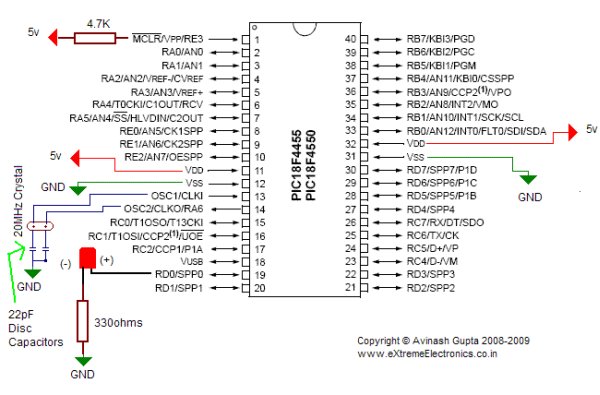
__CONFIG(1,0x0F24);
__CONFIG(2,0X0000);
in the C file of previous tutorial.
The chips is now ready for some amazing lighting effects !
Get the following to see that in action
A Breadboard.
A 20MHz Crystal
1 x 330 Ohms resistor
1 x 4.7k resistor.
2 x 22pF Ceramic Disk Type Capacitor.
A LED
Some Bread boarding wires (free if you buy Breadboard from above link)
Go ahead and connect them like this.
For more detail: Hello World Project With PIC Microcontroller – Part II
About The Author
Ibrar Ayyub
I am an experienced technical writer holding a Master's degree in computer science from BZU Multan, Pakistan University. With a background spanning various industries, particularly in home automation and engineering, I have honed my skills in crafting clear and concise content. Proficient in leveraging infographics and diagrams, I strive to simplify complex concepts for readers. My strength lies in thorough research and presenting information in a structured and logical format.
Follow Us:LinkedinTwitter