
For microcontrollers, an LED blinking program is equivalent to the “hello world” program. In our previous tutorial, we learned how to get started with STM8S103F3 Development Board and how to set up the IDE and compiler to program our STM8S controllers. We have also learned how to use the standard peripheral libraries, and how to compile and upload the code into our microcontroller. With all the basics covered, lets actually start writing code. In this tutorial, we will learn how to perform general GPIO functions on STM8S controllers. The board already has an onboard LED connected to pin 5 of port B, we will learn how to blink this LED and also add an external LED and control it with a push-button. If you are completely new, it is highly recommended to read the previous tutorial before you proceed any further.
Getting the Hardware Ready
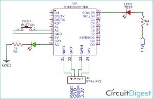
Before we dive into the program, let get the hardware connections ready. As mentioned early, we will be using two LEDs here, one is an onboard LED which will blink continuous and the other is an external LED which will be toggled with a push button. The idea is to learn all the GPIO functionality in a simple set up. The on-board Led is already connected to PB5 (pin5 of PORTB), so I have just connected an LED to PA3 and a push-button to PA2, as you can see in the diagram below.
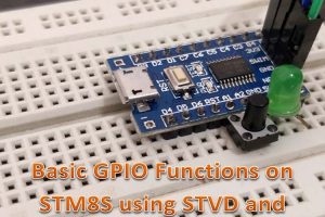
But, of all the output pins available on our controlled why did I select PA3 for output and PA2 for input? The questions are valid and I will explain that later in this article. My hardware set-up for this tutorial is shown below. As you can see, I have also connected my ST-link programmer to programming pins which will not only program our board but will also act as a power source.
Understanding GPIO Pinouts on STM8S103F
Now coming back to the question, why PA2 for input and why PA3 for output? To understand that, let’s take a closer look at the pinout of the microcontroller which is shown below.
As per the pinout diagram, we have four ports on our microcontroller, namely, PORT A, B, C, and D denoted by PA, PB, PC, and PD respectively. Each GPIO pin is also clubbed with some other special functionality. For example, the PB5 (pin 5 of PORT B) can not only work as a GPIO pin but also as an SDA pin for I2C communication and as a Timer 1 output pin. So, if we use this pin for simple GPIO purposes like connecting an LED, then we won’t be able to use I2C and the LED at the same time. Sadly, the on-board LED is connected to this pin, so we don’t have much of a choice here, and in this program, we are not going to use I2C, so it’s not much of a problem.
Pinout Description and Tips for STM8S103F GPIO Selection
Truly speaking, it would not hurt to use PA1 an input pin and it would just work pin. But I deliberately brought this up to provide me an opportunity to show you some common traps that you might fall into when selecting GPIO pins on a new microcontroller. The best to avoid the traps is to read the pin details and pin description provided in the STM8S103F3P6 datasheet. For the STM8S103F3P6 microcontroller pin description details that are mentioned in the datasheet are shown below images.
The input pins on our microcontroller can either be floating or weak pull-up and the output pins can either be Open Drain or Push-pull. The difference between Open Drain and Push-Pull Output pins is already discussed, hence we won’t get into details of that. To put it simple, an Open Drain output pin can make the output only as low not as high, while a push-pull output pin can make the output both as high as well as high.
Apart from that from the above table, you can also notice that an output pin can either be Fast output (10 Mhz) or Slow Output (2 MHz). This determines the GPIO Speed, if you want to switch your GPIO pins between high and low very fast, then we can choose Fast output.
Some GPIO pins on our controller support True Open Drain (T) and High Sink Current (HS) as mentioned in the above image. A considerable difference between Open Drain and True Open Drain is that the output connected to open drain cannot be pulled high more than the operating voltage of microcontroller (Vdd) while a true open-drain output pin can be pulled higher than Vdd. Pins with High Sink Capability means that it can sink more current. The source and sink current of any GPIO HS pin is 20mA, while the power line can consume up to 100 mA.
Taking a closer look on the above image, you will notice that almost all GPIO pins are High Sink Current (HS) type except for PB4 and PB5 which are True Open Drain Type(T). This means that these pins cannot be made high, they will not be able to provide 3.3V even when the pin is made high. This is why the onboard led is connected to a 3.3V and grounded through PB5 instead of powering it directly from the GPIO pin.
Source: GPIO Functions on STM8S using Cosmic C and SPL – Blinking and Controlling LED with Push Button
About The Author
Muhammad Bilal
I am a highly skilled and motivated individual with a Master's degree in Computer Science. I have extensive experience in technical writing and a deep understanding of SEO practices.