This is our 10th tutorial of Learning PIC microcontrollers using MPLAB and XC8. Till now, we have covered many basic tutorials like LED blinking with PIC, Timers in PIC, interfacing LCD, interfacing 7-segment, ADC using PIC etc. If you are an absolute beginner, then please visit the complete list of PIC tutorials here and start learning.
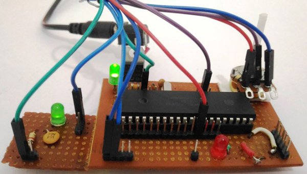
In this tutorial, we will learn How to generate PWM signals using PIC PIC16F877A. Our PIC MCU has a special module called Compare Capture module (CCP) which can be used to generate PWM signals. Here, we will generate a PWM of 5 kHz with a variable duty cycle from 0% to 100%. To vary the duty cycle we are using a potentiometer, hence it is recommended to learn ADC tutorial before starting with PWM. PWM module also uses timers to set its frequency hence learn how to use timers beforehand here. Further, in this tutorial we will use a RC circuit and a LED to convert the PWM values to Analog voltage and use it for dimming the LED light.
What is a PWM Signal?
Pulse Width Modulation (PWM) is a digital signal which is most commonly used in control circuitry. This signal is set high (5v) and low (0v) in a predefined time and speed. The time during which the signal stays high is called the “on time” and the time during which the signal stays low is called the “off time”. There are two important parameters for a PWM as discussed below:
Duty cycle of the PWM:
The percentage of time in which the PWM signal remains HIGH (on time) is called as duty cycle. If the signal is always ON it is in 100% duty cycle and if it is always off it is 0% duty cycle.
Duty Cycle =Turn ON time/ (Turn ON time + Turn OFF time)
Frequency of a PWM:
The frequency of a PWM signal determines how fast a PWM completes one period. One Period is complete ON and OFF of a PWM signal as shown in the above figure. In our tutorial we will set a frequency of 5KHz.
PWM using PIC16F877A:
PWM signals can be generated in our PIC Microcontroller by using the CCP (Compare Capture PWM) module. The resolution of our PWM signal is 10-bit, that is for a value of 0 there will be a duty cycle of 0% and for a value of 1024 (2^10) there be a duty cycle of 100%. There are two CCP modules in our PIC MCU (CCP1 And CCP2), this means we can generate two PWM signals on two different pins (pin 17 and 16) simultaneously, in our tutorial we are using CCP1 to generate PWM signals on pin 17.
The following registers are used to generate PWM signals using our PIC MCU:
- CCP1CON (CCP1 control Register)
- T2CON (Timer 2 Control Register)
- PR2 (Timer 2 modules Period Register)
- CCPR1L (CCP Register 1 Low)
Programming PIC to generate PWM signals:
In our program we will read an Analog voltage of 0-5v from a potentiometer and map it to 0-1024 using our ADC module. Then we generate a PWM signal with frequency 5000Hz and vary its duty cycle based on the input Analog voltage. That is 0-1024 will be converted to 0%-100% Duty cycle. This tutorial assumes that you have already learnt to use ADC in PIC if not, read it from here, because we will skip details about it in this tutorial.
So, once the configuration bits are set and program is written to read an Analog value, we can proceed with PWM.
The following steps should be taken when configuring the CCP module for PWM operation:
- Set the PWM period by writing to the PR2 register.
- Set the PWM duty cycle by writing to the CCPR1L register and CCP1CON<5:4> bits.
- Make the CCP1 pin an output by clearing the TRISC<2> bit.
- Set the TMR2 prescale value and enable Timer2 by writing to T2CON.
- Configure the CCP1 module for PWM operation.
For more detail: Generating PWM using PIC Microcontroller with MPLAB and XC8
About The Author
Ibrar Ayyub
I am an experienced technical writer holding a Master's degree in computer science from BZU Multan, Pakistan University. With a background spanning various industries, particularly in home automation and engineering, I have honed my skills in crafting clear and concise content. Proficient in leveraging infographics and diagrams, I strive to simplify complex concepts for readers. My strength lies in thorough research and presenting information in a structured and logical format.
Follow Us:LinkedinTwitter