This is an electronic garage door opener designed around a SparkFun GT-511C1R fingerprint scanner. There is already a very good instructable by user nodcah that describes how to build almost this exact device, from which I took 99% of my inspiration. I’m posting this to easily share with my local makerspace, and for anyone who likes to see things done slightly differently.
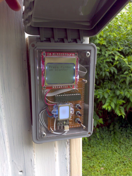
The door opener system consists of two components: a control panel on the outside of the garage with the fingerprint scanner, a small screen, and some buttons in a weatherproof housing; and a small box inside the garage that verifies when a recognized fingerprint has been scanned and opens the door, and also converts whatever power you provide into 3.3 Volts. An ATMega328p microcontroller is the brains of the exterior control panel, and an ATTiny lives in the box inside the garage. The two MCUs communicate over a serial connection. The ATTiny biases a transmitter to close the connection for the garage door switch when it receives a specific code phrase over the serial connection. This way a mildly clever vandal can’t break into the garage by ripping off the control panel and crossing a couple wires.
Though the datasheet claims this FPS can handle up to 6 Volts, I’m skeptical since the better model requires 3.3, and since the MCUs are happy with 3.3 Volts and the LCD requires it we’ll just power the whole thing that way.
Parts List:
- GT-511C1R Fingerprint Scanner (make sure to buy the JST connector too)
- Nokia 5110 LCD
- ATMega328p microcontroller
- ATTiny85 microcontroller
- MCP1700-3V3 voltage regulator
- 10 uF capacitor (2)
- 10 kOhm resistor (3)
- 100 Ohm resistor (3)
- tall momentary pushbutton (3)
- ic sockets, 28-pin and 8-pin, protects MCUs when soldering and nice if you want to reprogram them
- terminal block, for connecting the control panel wires to the interior box without the need to solder
- weatherproof exterior utility box, like this one maybe
- a small rectangular piece of acrylic for the front cover of the control panel to keep things classy
- 5V DC converter, such as a phone charger
Use the attached schematic to solder together the circuits for the control panel and interior module on some protoboard or however you like to roll. You will solder the JST connector and some flying wires (I found ribbon cable keeps things organized) for the FPS and LCD, so they can hang loose and be secured to the front panel of the control panel. Examining the code in later steps will reveal that the buttons wired to pins 12, 13, and 14 (i.e. Arduino pin 6, 7, and 8) serve the functions “up”, “OK”, and “down”, respectively. So, you may want to arrange them this way on the board to keep things nice and logical.
I cut the microUSB connector off of an extra phone charger to power everything, since they’re cheap and easy to come by if you stay away from the Apple Store. You could run the whole thing with batteries (although don’t give too much voltage to the poor little MCP1700 or he’ll get hot), but the FPS must drain a lot of power because when I tried it with 3xAAA it only worked for about a day.
The two modules are connected by three wires – one for 3.3V, one for ground, and one from TX on the ATMega328p to pin 5 (aka Arduino pin 0) on the ATTiny, which will be RX for a software serial connection. Twisting them together makes them easier to thread through and looks neato.
For more detail: Garage Door Fingerprint Lock
About The Author
Ibrar Ayyub
I am an experienced technical writer holding a Master's degree in computer science from BZU Multan, Pakistan University. With a background spanning various industries, particularly in home automation and engineering, I have honed my skills in crafting clear and concise content. Proficient in leveraging infographics and diagrams, I strive to simplify complex concepts for readers. My strength lies in thorough research and presenting information in a structured and logical format.
Follow Us:LinkedinTwitter