 Theory
An ICD is a hardware device that is connected between a PC and the target microcontroller to debug real-time applications quickly and easily. The ICD is controlled by a debugging application tool running on the PC. The debugging tool allows the designer to slow down the microcontroller operation by inserting breakpoints into the program 0r single-step the program execution. After the execution of a single or a group of instructions, the values of the program variables and internal registers can be examined, and modified if required. This helps to quickly identify bugs and errors in the source code and thus expedite the development process of the project.
ICD in PICMicro
In PIC microcontrollers, in-circuit debugging is achieved through the same pins that are used for In-Circuit Serial Programming (ICSP), i.e. ICSPDAT (or PGD), ICSPCLK (or PGC), VPP/MCLR (programming mode voltage), VDD (power supply voltage), and VSS (Ground). This allows manufacturers to integrate ISCP programming and in-circuit debugging features into a single device. During debugging, the ICD device adds an additional block of code (along with the user application) to the target microcontroller’s program memory, which interacts with the debugging application and sends variable values, internal register values and other details to the PC through the same programming cable.
For example, Microchip’s MPLAB ICD2 and ICD3 are both programmer and real-time debugger for selected PIC MCUs and dsPIC DSCs. The functionality of the ICD is controlled by the MPLAB Integrated Development Environment (IDE) application software running on the PC. During debugging all available features of the target microcontroller are accessible interactively through the MPLAB IDE interface. These functions allow you to run the program in single-step mode, insert breakpoints into the program, examine the registers and variables, and modify them if desired.
Although an ICD is an invaluable debugging tool, it does not come at no cost. The two main disadvantages of ICD are: 1) it uses some memory of the target microcontroller, and 2) it occupies a few I/O pins of the target microcontroller to communicate with the PC. Therefore, while debugging, the PGD, PGC, and MCLR pins of the target microcontroller cannot be used for any other purposes.
PICFlash with mikroICD
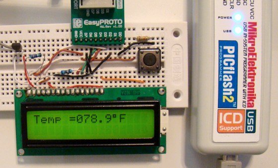
The PICFlash with mikroICD is a programmer and in-circuit debugger for PIC12, PIC16, and PIC18 series microcontrollers. It is manufactured by mikroElektronika and is supported by all of its PIC compilers (mikroC, mikroBasic, and mikroPascal). The device communicates with PC through an USB interface, which also provides the necessary power for the ICD. ?It connects to the target PIC microcontroller through the PGC, PGD, VPP/MCLR and power supply pins. When this device is used as an standalone programmer, the first three pins are released after the HEX file is loaded into the target PIC microcontroller. But if it is used for in-circuit debugging, those three pins are used for communicating with the PC and hence cannot be used for any other purposes.
Installing software for PICFlash with mikroICD
You can find the detail information about this in the mikroICD manual. The easiest way to setup this device is to download the PIC compiler first. Note that this device does not work with any other party’s compiler, so you need one of mikroElektronika compilers to make it work. The following steps describes the software installation and setup of PICFlash with mikroICD for mikroC Pro for PIC compiler.
- First, download mikroC Pro for PIC compiler from HERE and install it on your PC.
- When the installation is complete, it will ask if you want to install mikroProg Suite for PIC. Say yes, and install that too.
- Next, it will ask if you want to install the drivers for mikroProg programmer. Say yes, and select the driver file suitable to your operating system, and install it. You are done!
 Using PICFlash with mikroICD for Debugging
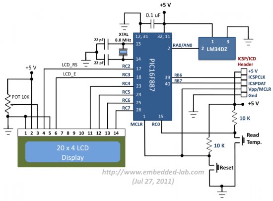
The first step of using the mikroICD is writing an application program in the chosen compiler, say mikroC Pro for PIC. The compiler’s IDE provides debugging functions such as running the program step by step, pausing the program execution using breakpoints, examining the state of the internal registers, tracking the values of variables in the program, etc. Please read the mikroICD manual for further detail. I will be illustrating the debugging procedure with our test project that uses PIC16F887 microcontroller and LM34DZ sensor to measure the ambient temperature and display it on LCD. The circuit diagram for this project is shown below and is self-explanatory. The way it works is every time the Read Temp. switch is pressed, the microcontroller reads the temperature sample from the LM34DZ and displays it on the LCD. You can see that under default condition, the switch output is High, and it goes Low when the switch is pressed. I am using mikroElektronika’s PIC Ready 1 board for this experimental setup. It is a quick prototyping board for 28 and 40 pin PIC microcontrollers. The board comes with a PIC16F887 microcontroller, preloaded with a serial bootloader, which is actually not applicable in our case. However, the board does contain connectors for PICFlash with mikroICD too. The user’s manual for PIC Ready 1 board describes more about the on-board connections.
About The Author
Ibrar Ayyub
I am an experienced technical writer holding a Master's degree in computer science from BZU Multan, Pakistan University. With a background spanning various industries, particularly in home automation and engineering, I have honed my skills in crafting clear and concise content. Proficient in leveraging infographics and diagrams, I strive to simplify complex concepts for readers. My strength lies in thorough research and presenting information in a structured and logical format.
Follow Us:LinkedinTwitter