
description
This is my electronic combination lock to use with an outdoor gate. The functionality is implemented in software. It turns on a relay (usually to open a door) for a few seconds if someone enters the valid code. Alternatively, it works as an ON/OFF switch, which toggles the relay each time the code is entered. This relay can operate a power-to-open type electric strike with a shorting contact or a power-to-hold type electromagnetic lock with a breaking contact (we need the relay because these locks usually work with AC, not DC). The code can be changed any time after entering the current code.
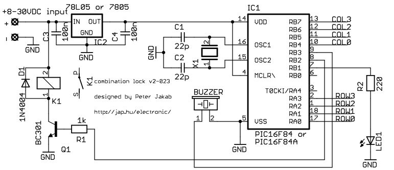
Current consumption of the circuit is low, because the PIC sleeps most of the time, and wakes up only for processing key presses. If you don’t have a crystal, you can use the RC oscillator of the PIC16F84 as well, just check the PIC datasheets for details on oscillator configurations. The 16F628 already contains an internal RC oscillator, so no crystal is needed.
operation
type in the correct code and use # as ‘enter’. The initial code is 1234 after programming the un-modified HEX file. You could activate the output with typing in:
1 2 3 4 #
* is used to change the code. Type in the actual code then press *. If you didn’t miss the actual code, the code change indicator LED will light up. Then type in the new code twice. Eg:
1 2 3 4 * 1 9 9 8 # 1 9 9 8 #
will change the code to 1998. The code changes immediately and permanently after typing the new code twice. If you miss entering the new code twice, the original code is kept.
software
Essentially, all software versions work the same. You can download and customize the source code for the version you choose. The first few lines of the code contain definitions of changeable parameters. If you are lazy, you can simply download the HEX files already compiled with default values. The definitions:
mhz EQU D'4' |
this value is used for delay calibration. Of course, the code will run with different speed hardware as well, but faster or slower than intended. |
pulsewidth EQU 'D'150' |
this value is used to set the delay of the output pulse. To calculate the delay in seconds, use pulsewidth * 20 ms |
clen EQU 4 |
this value sets the length of the code. The length is always fixed, and you can set it much higher, until you have available RAM on the chip |
More details on the source code can be found here.
hardware
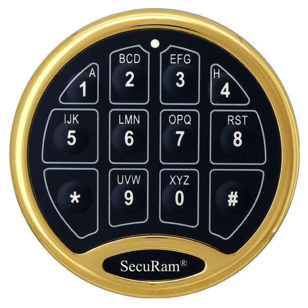
The keypad is actually a collection of push-buttons, organized into a matrix. It looks like this:
For more detail: Electronic combination lock based on PIC16f84
About The Author
Ibrar Ayyub
I am an experienced technical writer holding a Master's degree in computer science from BZU Multan, Pakistan University. With a background spanning various industries, particularly in home automation and engineering, I have honed my skills in crafting clear and concise content. Proficient in leveraging infographics and diagrams, I strive to simplify complex concepts for readers. My strength lies in thorough research and presenting information in a structured and logical format.
Follow Us:LinkedinTwitter