This Electromagnetic levitation device is a cool to build an anti-gravity project that is exciting and interesting to watch. The device can make something float without any visible support, it is like an object swimming in free space or air. To make this device work, you need to attract an object using the electromagnet, but when it is very close to the electromagnet, the electromagnet should deactivate and the attracted object should fall down due to gravity and again attract the falling object before it falls down completely due to gravity and this process continues. The project is similar to our Ultrasonic Acoustic Levitation, but here instead of using ultrasonic waves, we will be using electromagnetic waves.
Now getting back to the concept, it is not possible for a human being to turn on and turn off the electromagnet because this switching process has to take place very fast and at a specified interval. So we have built a switching circuit, which controls the electromagnet to achieve electromagnetic floating.
Component Required
| S.No | Parts/Component Name | Type/Model/Value | Quantity |
| 1 | Hall Effect Sensor | A3144 | 1 |
| 2 | Mosfet Transistor | Irfz44N | 1 |
| 3 | Resistance | 330ohm | 1 |
| 4 | Resistance | 1k | 1 |
| 5 | Indicating L.E.D | 5mm any color | 1 |
| 6 | Diode | IN4007 | 1 |
| 7 | 26 or 27 Gauge Magnet wire | 0.41 to 0.46 mm | 1kg or more |
| 8 | Dotted Vero board | Small | 1 |
Magnetic Levitation Circuit Diagram
The complete Magnetic Levitation Schematic can be found below. As you can see it only consists of few normally available components.
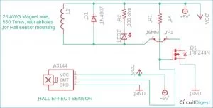
The main components of this DIY Magnetic levitation circuit are the Hall effect sensor and MOSFET transistor and an electromagnetic coil. We have previously used electromagnetic coils to build other interesting projects like a Mini Tesla Coil, an Electromagnetic coil gun, etc.
We use Irfz44N N-channel Mosfet for very first switching and turning the electromagnets on/off. Irfz44n / any N-channel MOSFET or similar (NPN) powerful transistor can be used for this purpose, which has high current handling capability like TIP122 /2N3055, etc. The Irfz44N transistor is chosen because it’s commonly used with 5V operated microcontroller projects and is easily available in the local markets. On the other hand, it has 49A Drain current handling capability at 25-degree temperature. It can be used with a wide range of voltages.
First, I have experimented and tested the circuit and the whole project on 12 Volt configuration, but I found my electromagnetic coil and MOSFET, both were getting extremely hot, so I had to switch back to 5v. I didn’t notice any difference or problems happening, and the MOSFET and coil were at normal temperature. Also, there was no need for the heat sink for the Mosfet.
The resistorR1 is used to keep the MOSFET gate pin voltage high (like a pull-up resistor) for getting proper threshold voltage or trigger voltage. But when the neodymium magnets are near to the center-mounted hall effect sensor (in the middle of electromagnets) or the neodymium magnets are within the range of hall effect sensor, our circuit should provide negative output to the MOSFET gate pin. As a result, get pin /control pin voltage drops, the MOSFET drain pin output for the indicator L.E.D., and electromagnet also drops, and it gets disabled. When the objects attached with neodymium magnets drop or fall because of the gravity, the Neodymium magnets will get out of the hall effect sensor range and now the hall effect sensor doesn’t provide any output. MOSFETs gate pin becomes high and quickly triggered on (for R1 resistance control pin /gate pin already high) energize the electromagnetic coil quickly and attract the object attached with neodymium magnets. This cycle continues, and objects remain hanging.
The R2 330ohm resistance is used for glowing LED at 5v (indicator LED) and limits the voltage and current flow for LED protection. The D1 diode is nothing but a feedback blocking diode used in every coil device like a relay for reversed feedback voltage blocking.
Building the Magnetic Levitation Circuit
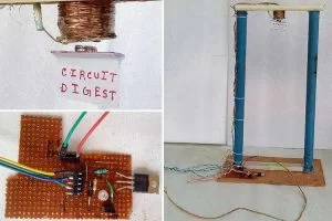
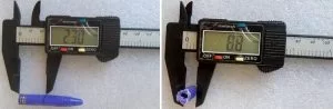
Start by building the coil for electromagnet. For the making of airhole Electromagnet, first, you need to make a frame or body for the electromagnets. To do that take an old pen of around 8mm diameter which already has a center hole (in my case, I have measured the diameter in Vernier scale). Mark the required length with a permanent marker and cut into 25mm length approximately.
Next, take a small piece of cardboard / any hard quality paper material, or you can use plexiglass and cut two pieces of winding diameter about 25mm length with a center hole as shown in the picture below.
Fix everything with the help of “feviquick” or with the help of any strong glue. Finally, the frame should look like this.
If you are too lazy to build this, you can take an old soldering wire holder.
The electromagnet frame is ready. Now move on to the making of an electromagnetic coil. First, make a little hole on one side of the winding diameter and fix the wire. Start winding the electromagnet and make sure it makes about 550 turns. Each layer is separated by cello tape or other types of tape. If you are so lazy to make your electromagnets (in my case, I have made my electromagnets which also have the advantage of working with 5v ), you can take it out from 6 v or 12 v relay, but you should be careful that your hall effect sensor A3144 only accepts the 5V maximum. So you need to use an LM7805 voltage regulator IC to give power to your hall effect sensor.
When your center air cored electromagnet coil is ready, keep it aside and move to step 2. Arrange all the components and soldered it on the Vero board, as you can see in the pictures here.
For fixing the electromagnetic coil and hall effect sensor setup, a stand is necessary because of the state alignment of the coil and sensor setup is important for the stable hanging of the object towards the gravity force. I arranged two pieces of pipe, cardboard, and a little piece of P.V.C. wiring casing. For marking the required length, I used a permanent marker and for cutting, I used a hand saw and a knife. And fixed everything with the help of glue and Glue Gun.
Make a hole in the middle of P.V.C. wiring casing and fix the coil with the help of glue. Thereafter, fold the sensor. Put inside the hole of the electromagnetic coil. Please keep in mind the distance of the hanging object (attached with neodymium magnets) from the electromagnetic coil depends on how much the sensor is pushed inside the center hole of the electromagnet. The hall effect sensor has a specific sensing distance, which should be within the electromagnetic attraction range to hang the objects perfectly. Our Homemade electromagnetic levitation device is now ready for action.
Source: DIY Electromagnetic Levitation Device
About The Author
Muhammad Bilal
I am a highly skilled and motivated individual with a Master's degree in Computer Science. I have extensive experience in technical writing and a deep understanding of SEO practices.