
Last year I started a project to convert my (then) four-year old’s busted Radio Controlled (RC) car into Bluetooth controlled one which could be driven using a smart phone or tablet. The original car, modeled after a “Fast and Furious” Nissan Silvia, was a pretty basic RC with 2-channel on-off (non-proportional) style controls, and while Micah enjoyed playing with it I thought it might be nice to pimp it out a bit and really make it a fun toy. Well actually, I thought at the very least it would be fun for me to try, even if I ended up making a bigger mess of it than it already was. It took a bit of work but I managed to pull it off, and while it had a couple of flaws, I thought it might be worth sharing my experiences for the benefit of any other hobbyist who might want to give this crazy experiment a try.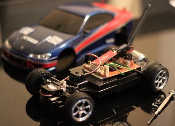
The concept was actually quite simple, nothing novel really and besides the Bluetooth interface the only other requirement was for the car to have proper proportional steering and acceleration because let’s face it, simple on-off controls are pretty boring. So this meant that I had to swap out the car’s simple DC motor steering mechanism and replace it with a proper micro-servo. Anyhow getting down to the specifics, at the heart of the device was an 8-bit PIC16F88 Microcontroller which was integrated with a BlueSMiRF Bluetooth serial modem from Sparkfun using the PIC’s UART module. The BlueSMiRF is great because it implements the RFCOMM protocol which basically emulates a 3-wire asynchronous serial port with TTL level signaling over the Bluetooth channel, hence it is transparent to the PIC which just sees it as a serial I/O device from which it receives control instructions and to which it can write diagnostic information. For communicating with the PIC I used a simple protocol based on 1-byte (8-bit) commands described in the below table. Bit-7 is currently unused.
The motor driver circuit is a design for a non-shorting H-bridge which uses a CMOS 2-4 line decoder, some discrete components, plus I’ve added diodes for back-EMF protection. At the time I didn’t have access to any monolithic H-bridge IC (e.g. the SN754410) so I borrowed this circuit since I figured if anything, the medium power transistors can handle up to 1.5A each and having four separate packages would provide better thermal dissipation than if they were lumped together in the same package. The speed (SPD) input of the H-bridge is driven by the PWM module of the PIC running at 10KHz, whilst the direction (DIR) input is just driven by a regular I/O port. At some point I’d like to add a feedback loop based on measurements of the motor’s back-EMF made via the PIC’s A/D converter, since this would allow for more precise motor speed control.
The servo is pulse input is driven by a software PWM signal generated using timer preset functionality of the Timer1 module along with overflow interrupts which do the actual bit-bashing out an I/O port. I suspect it might even be possible to multiplex control of up to 7 servos (using other I/0 ports) within this software routine, given that each pulse has a maximum length of 2.7ms and are spaced at 20ms apart.
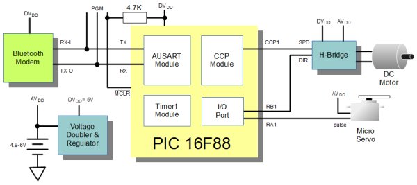
My understanding is that normally for robotics projects, digital devices (e.g. PIC controllers) are run off a separate power supply (or in the case of battery-powered ones, different cells) from noisy analog devices, motors being the worst of these. However, because I intended on leveraging the existing 4 x AA battery compartment in the car, this wasn’t going to be an option for me, since I would need at least an additional 2 x AA cells just for the digital circuits. Now the PIC 16F88 required at least 4V and I wanted to use 1.2V nickel-cadmium rechargeable cells, which meant the car would have to work with 4.8V minimum. So at first I thought I could get away with connecting the motors and digital circuits to the one common 4.8V supply and just regulate and filter power going to the PIC, but as it turned out the DC motor consumed large start-up and stall currents resulting in as much as 1V dips in the supply voltage and this caused the digital circuits to brownout.
For more detail: DIY Bluetooth RC Car
About The Author
Ibrar Ayyub
I am an experienced technical writer holding a Master's degree in computer science from BZU Multan, Pakistan University. With a background spanning various industries, particularly in home automation and engineering, I have honed my skills in crafting clear and concise content. Proficient in leveraging infographics and diagrams, I strive to simplify complex concepts for readers. My strength lies in thorough research and presenting information in a structured and logical format.
Follow Us:LinkedinTwitter