
Digital thermometers are cool devices as they show temperatures in human readable formats. This digital thermometer project is based on a PIC16F688 microcontroller and a DS1820 temperature sensor, and it displays temperature on a character LCD screen in both Celsius and Fahrenheit scales. I selected PIC16F688 for this project because it is cheap (I bought one for $1.50). DS1820 is a 3-pin digital temperature sensor from Dallas semiconductors (now Maxim) which is designed to measure temperatures ranging from -55 to +125 °C in 0.5 °C increments. The firmware I have written is able to read and display the entire temperature range of DS1820. In order to test for temperature measurements below 0°C, I put the sensor inside my freezer. While trying this, don’t put the whole unit inside the freezer as LCD display unit may stop working at the freezer temperature. Similarly, bringing a soldering iron tip close to the sensor can do testing for the higher range temperature values.

About DS1820
I suggest reading my previous articles on DS1820 for getting details about this 1-wire temperature sensor. The firmware that I wrote works only for DS1820 (it may work for DS18S20 making some change in the temperature conversion time, read http://www.maxim-ic.com/datasheet/index.mvp/id/3021). It will definitely not work for DS18B20.
DS1820 converts temperature in to a 9-bit digital word, which is read by PIC16F688 as two bytes (TempH and TempL). The value of the least significant bit is 0.5°C. For positive temperature, the next eight bits after the LSB gives the integer part of the temperature. For example, 000110011 represents 25.5°C. Further, the floating-point math can be avoided during C to F conversion by using a scale factor of 10. Therefore, 25.5°C (scaled 255) is converted to F as,
However, the negative temperatures are stored in 2’s complement form. So the most significant bit of the 2-byte temperature reading from DS1820 is 1 if the temperature is below 0°C. The firmware takes care of all negative temperature readings (in both C and F scales). The computed temperature is displayed on LCD as a 5-digit string array, xxx.x (e.g., 24.5, 101.0, -12.5, etc).
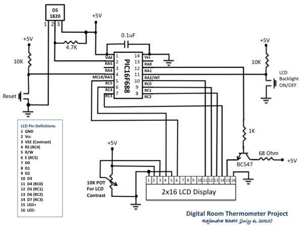
Circuit Diagram
The circuit diagram of this project is shown below. DS1820 sensor output is read by PIC16F688 through RA5 port. The computed temperature is converted to a string and sent to the LCD to display. The LCD is operating in 4-bit mode, and ports RC0-RC3 serves D4-D7 data pins of the LCD. The Register Select (RS) and Enable (E) signals for LCD are provided through ports RC4 and RC5. The Read/Write pin of the LCD is permanently grounded, as there is no data read from the LCD in this project. The contrast adjustment of LCD is done with the 10K potentiometer shown in the circuit diagram.
For more detail: Digital Thermometer Using PIC16F688 microcontroller
About The Author
Ibrar Ayyub
I am an experienced technical writer holding a Master's degree in computer science from BZU Multan, Pakistan University. With a background spanning various industries, particularly in home automation and engineering, I have honed my skills in crafting clear and concise content. Proficient in leveraging infographics and diagrams, I strive to simplify complex concepts for readers. My strength lies in thorough research and presenting information in a structured and logical format.
Follow Us:LinkedinTwitter