
Hello everyone, thank you for checking out my first Instructable. I have enjoyed seeing your creations over the years and love what all of you are contributing. This project is a spin off of one that I recently saw here and I need to give a shout out to Bot1398 because he demonstrated to me in his Instructable that you could use an LED to detect changes in light intensity in the environment and use this to turn another LED on or off. I knew that if you supplied a little bit of power to an LED it would emit light. I never thought it could be used the other way around. After I saw his Instructable: Light Sensing LEDs it made sense but I wanted to see this actually work for myself.
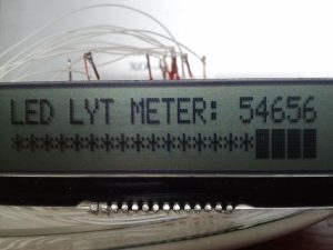
I am writing this Instructable because Bot1398 used an Arduino and I’ve never used them. I have nothing against them, however, when I started using microcontrollers about 3 years ago I was looking for speed and power for a specific application. I settled on the PIC Microcontroller series by Microchip. It is amazing what you can do with microcontrollers, you can let your imagination run wild and with a little creative programming achieve exactly what you want. There are a number of programming languages out there as well but when I started I wanted speed and to know exactly what was going on at each and every step, therefore, I chose Assembly Language since it seemed a lot like BASIC that I learned on the IBM PC Jr. back in the 1980’s when I was growing up. That is what this Instructable entails: PIC Microcontrollers and Assembly Language to use an LED (Light Emitting Diode) to detect the amount of ambient light and display the numerical measure of this light along with a bargraph on an LCD screen.
I did produce the first version of this LED-based Light Sensing device which did work, the trouble that I noticed was that the values jumped around quite a bit. Therefore, I looked for a solution to this problem I thought about averaging the values, but how? Binary math does is kind of difficult but there is always a way to get it done. As I was searching for solutions I came across a great page about Moving Averages and how to do it most effectively so that even the 8-Bit Microcontrollers can handle it with ease. The link to the page is here: Computationally Efficient Moving Averages and this works extremely well. This implementation displays the Moving Average of the last 256 light readings and displays that value along with a bargraph on the LCD Screen. The moving average code prevents the values read from the LED from jumping around much and gives you a better, much more accurate result.
Why This Works
When we attach an LED to a Microcontroller we are usually doing that to light it up. In this case, however, we are actually applying a positive voltage to the negative end of the electrode. This is so we can take advantage of something called parasitic capacitance. Applying this positive voltage will build up a small charge (resources on the internet say within about 100-200 nanoseconds) within this parasitic capacitance of the LED that we are using. The actual capacitance is not very important but online resouces say that it is around 10-15 pF. We will then switch the pin of the microcontroller attached to the negative end of the electrode from an OUTPUT to an INPUT and wait for the charge to drain. When charge drains enough the pin will now read a Logic Level 0 or Low state where we will turn off the timer and use this value to calculate the moving average and display the results on the screen. We will then take more readings and display them on the screen at the interval that is written in the assembly code. In the finished code, I have it set to take one reading about every 20 or so microseconds. This occurs 50 times so that an updated result is displayed on the screen approximately every second or so. The time it takes to get a reading will vary a little bit because it takes longer for the charge to drain in a dark environment and this occurs faster in light environments. The discharge rate of the LED capacitance is somehow directly related to the number of photons or amount of light striking the LED light generating elements. Neat isn’t it. 🙂
Now that we know how it works, let’s move on to Step #1.
Step 1: Gather Components and Assemble the Circuit
First gather the following items you will need to build the LED LYT METER:
PIC Microcontroller (I used the 18F4550)
LCD Screen (2×20 or 2×16)
LEDs
Breadboard
Wires
Power Source
Now you should be able to follow the schematic to assemble the circuit on a breadboard or any other way that you like to put your circuits together. This one is fairly easy and has minimal parts. I did attach two different schematics, the one has the light measuring LED connected to two different microcontroller pins and the other one has this LED with the cathode (or negative end) connected to a microcontroller pin and the anode (or positive end) of the LED connected to ground. This seems backwards but, remeber, we are not using the LED to produce light, but to measure it instead. That is why it is connected in this way. In my pictures you will see that the LED is connected to two pins of the microcontroller. This is because I wanted to be able to use the LED to produce light too, in order to check to make sure it works when the program is started.
If you do choose to connect the LED to 2 pins of the microcontroller you will need to keep this in mind for it to work. I could not find this documented anywhere so it took a little experimentation to get it to work. In order to be able to light up the LED both microcontroller pins will need to be set as OUTPUTS. Then, to make the LED shine, you set the anode (or positive end) of the LED high so that current flows through the LED to produce light. At first I thought that I would need to set the cathode (or negative end) of the LED as an INPUT but this did not work.
Now that you have the componenets, put them together on the breadboard by following the schematic you want to follow. When assembled, it should look somewhat similar to the pictures below. I am using a 5 Volt Regulator to supply 5 volts to power the circuit. I use a ‘wall wart’ that supplies about 9 volts to the regulator.
The LCD screen that I am using is a Newhaven Display NHD‐C0220AZ‐FSW‐FTW COG (Chip‐on‐Glass) Liquid Crystal Display Module. I used to use the HD44780 LCD displays that many other people use. You can definiately use the HD44780 displays without any problem and there is a lot more source code out there to make them run. The Newhaven display had no source code but sitting down with the data sheet and using the HD44780 source code, I came up with the code to make it work perfectly. I like the display for a few reason. The contrast is very easy to set and so far I have not had to change it at all during the different seasons, it always remains clear and very easy to read. It also has a smaller footprint and was exactly what I needed for a huge project that I am working on where available space is at a premium. It is smaller and than the HD44780 displays and still displays 20 characters on each of the two lines. Finally, it is less expensive than the HD44780 displays as well. I picked a couple of these up from Digikey and at only a price of $10.25 each. Check them out here: Newhaven LCD Display at Digikey. Keep in mind that this display requires from 3.3 to 5.5 volts so keep that in mind when choosing your power source. The source code that is supplied should also run the HD44780 displays without any problems.
This is just the way that I have it set up. You can place the components to diffent pins of your microcontroller. Just keep in mind which pins of the microcontroller you connect to the positive and negative end of the light sensing LED. You can also wire up your LCD screen to operate in 4-bit mode instead of 8-bit mode as illustrated. That would require four less connections in the circuit but makes your programming just slightly more complicated.
On to next steps…Writing the Program.
Source: Digital multimeter circuit using pic microcontroller
About The Author
Ibrar Ayyub
I am an experienced technical writer holding a Master's degree in computer science from BZU Multan, Pakistan University. With a background spanning various industries, particularly in home automation and engineering, I have honed my skills in crafting clear and concise content. Proficient in leveraging infographics and diagrams, I strive to simplify complex concepts for readers. My strength lies in thorough research and presenting information in a structured and logical format.
Follow Us:LinkedinTwitter