
Here is a simple project on how to control fan or dc motor speed with microchip pic16f877 microcontroller. There are numerous ways to control the speed of motor(or fan). Varying current, voltage and resistance etc. But when it comes to controlling the speed using microcontrollers. Then the PWM (Pulse width modulation) technique is most effective one. Pulse width modulation reduces the direct current/voltage pulse duration, which ultimately reduces the output current and voltage at output. In pulse width modulation the digital signal high and low time period is varied to output a desired voltage. Varying the dc voltage in pulses is know as duty cycle. A typical pulse width modulation diagram is show below with different duty cycles.
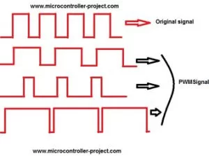
Varying duty cycle signals are shown in the pic on the right side. High pulse is generally termed as duty cycle. Original signal high pulse is 65% and low 35%. Thus original signal duty cycle is 65%. The work is only done in duty cycle period. Varying duty cycle signals are shown below the original. Duty cycle of easy signal is different then others. 70%, 30% and 90% respectively.
Pic microcontroller speed control project requirements
- Pic16f877 microcontroller
- L293d h-bridge Motor driver Ic
- DC Motor or small fan
- Crystal 20MHz
- Push Buttons
- connecting wires
- Bread board or PCB
- Power Supply battery
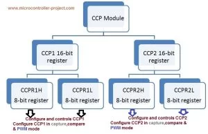
Registers associated with CCP1 & CCP2 Module.
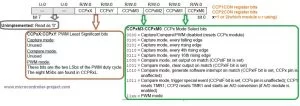

Note: Only Timer 2 can be used for PWM generation in Pic16f877.
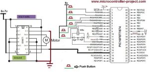
The circuit diagram of the project is given below. Six Push buttons are attached with port A of the pic16f877 microcontroller. These push buttons are used to change the speed of the motor. Their are six speed levels press these push buttons to change the speed of fan or motor. CCP1 pin is attached to L293d pin no 10. The motor rotates in anti clock wise direction when power is turn on. You can drive the motor in clock wise direction, just connect CCP1 with pin 15 of L293d and make pin 10 ground. 20 Mhz crystal is used in the project. Using a crystal of low frequency can also effect the motor speed.
In rundutycycle() function pwm signal in generated. The function of each instruction is given with it. The status of switches s1 to s6 are also checked in this function and duty cycle is varied according to the switches status. T2CON is timer 2 control register. To set its bit functions please refer to the data sheet of pic 16f877 microcontroller.
#include<htc.h>
#include<pic.h>
#define _XTAL_FREQ 20000000
void rundutycycle(unsigned int x );
#define s1 RA0
#define s2 RA1
#define s3 RA2
#define s4 RA3
#define s5 RA4
#define s6 RA5
void main()
{
ADCON1=0x06; //All pins as digital
TRISA=0b111111; //PortA as Input
TRISC2 = 0; //Make CCP1 pin as output
CCP1CON = 0x0C; //Configure CCP1 module in PWM mode
PR2 = 0xFF; //Configure the Timer2 period
rundutycycle(512);
}
void rundutycycle(unsigned int dutycyc){
T2CON = 0x01; // Set Prescaler to be 4, hence PWM frequency is set to 4.88KHz.
T2CON |= 0x04; // Enable the Timer2, hence enable the PWM.
while(1){
CCPR1L = dutycyc>>2; // Put MSB 8 bits in CCPR1L
CCP1CON &= 0xCF; // Make bit4 and 5 zero
CCP1CON |= (0x30&(dutycyc<<4)); // Assign Last 2 LSBs to CCP1CON
if(s1==1){dutycyc=172; }
if(s2==1){dutycyc=342; }
if(s3==1){dutycyc=512; }
if(s4==1){dutycyc=686; }
if(s5==1){dutycyc=858; }
if(s6==1){dutycyc=1020; }
dutycyc=dutycyc;
}
}
Download the project code, hex file(code) and simulation. Folder includes all the project files. The code is compiled using htc(high tech c compiler) and mplab . Simulation is made in proteaus 8.0.Please give us your feed back on the project.
About The Author
Muhammad Bilal
I am a highly skilled and motivated individual with a Master's degree in Computer Science. I have extensive experience in technical writing and a deep understanding of SEO practices.