
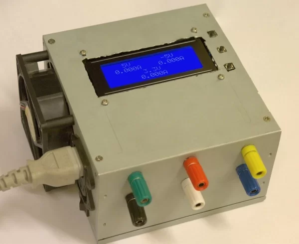
In this instructable I’m going to show you how to convert an old ATX power supply to a bench power supply that also displays the current drawn for each voltage rail on an LCD display.
Features:
The PSU uses a 20×4 LCD display to show the current readings for every voltage rail. But because the screen is too small to fit all five readings the same time, a momentary switch is used to select between viewing the currents from the 5V, -5V and 3.3V rails or from 12V and -12V rails.
A second momentary switch is used to turn on or off the backlight of the LCD.
A third momentary switch is used to power on the PSU or put it into stand by mode. In order for the microcontroller to been able to do that, it needs to have power even when the PSU is into stand by. For that reason it is powered from the 5V Stand By signal of the PSU. That way even when the PSU is into stand by mode the microcontroller still has power.
The microcontroller also monitors the Power Good signal and until it goes high it displays four stars “* * * *” on the screen to indicate to the user that the PSU is not ready. Also, the microcontroller starts to read the current sensors only after the Power Good signal goes high.
Step 1: The Parts
The parts you need are the following:
- 1 x ATX power supply. It can be any old (or new) ATX PSU.
- 1 x 5Ω resistor with 10W rating (for older PSUs) or 1 x 22Ω resistor with 10W rating (for newer PSUs). If you can’t find 10W resistors you can also use two 10Ω resistors with 5W rating in parallel, or two 47Ω resistors with 5W rating. If you are not sure if you need a 5Ω or a 22Ω resistor don’t worry I’ll explain it further later.
- 6 x Female banana connectors. One for each of the voltages of the PSU plus one for ground.
- Heat shrink tubing and electrical tape.
- 1 x 20×4 character LCD display.
- 4 x Female to female brass standoff spacers plus 8 screws for them. Alternatively you can use 4 female to male spacers plus 4 screws and 4 nuts.
- 3 x Momentary switches.
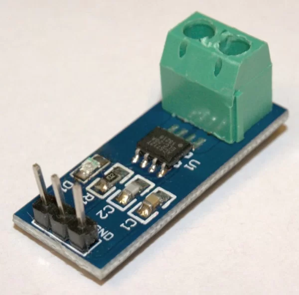
- 5 x ACS712 current measuring modules. There are three types of ACS712 modules. The 5A type, the 20A and the 30A. Personally, I used two 5A, one 20A and two 30A modules because my PSU can deliver a maximum of 28A on the 3.3V rail, 35A on the 5V, 16A on the 12V, 0.3A on the -5V and 0.8A on the -12V. But the problem is the higher the maximum current the hall sensor can measure the lower its sensitivity, and that leads to lower resolution of the measurement. So, when you use a 30A module to measure small currents the reading can be very inaccurate, I’m taking about ±75mA of error. For that reason even though your PSU most probably can deliver way more than 5A in most of its rails I recommend using the 5A modules for all the rails because most of the time when we work with electronics we don’t work with high currents, so it is worth to have better resolution than been able to measure currents more than 5A.
- Several female to female jumper wires.
- 4 x 1K Resistors with 1/4W rating
- 1 x 10K Resistor with 1/4W rating
- 1 x 10K Trimmer pot
- 1 x 220Ω Resistor with 1/4W rating
- 1 x 8Mhz Crystal
- 3 x 2N3904 Transistors
- 2 x 22pF Capacitors
- 1 x 100nF Capacitor
- 1 x 2.54mm 40Pin male 90° angle pin header: You are going to cut it in 3 pieces of 2 pins, one of 6 and one of 5.
- 1 x 2.54mm 16Pin male pin header for the LCD display if it doesn’t already have one soldered: If you can’t find one in that size you can get a bigger and cut it.
- 1 x 2.54mm 16Pin female pin header: If you can’t find one in that size you can get a bigger and cut it.
- 1 x PIC16F876A microcontroller in SPDIP package: You can use a SOIC or SSOP package if you want, but you will have to modify the schematic and the board layout.
- 1 x 72x50mm PCB photoresist or bare copper board plus all the materials need to etch the PCB depending on the etching method you are going to follow. Or, if you prefer not to etch a PCB then you can just use a prefboard.
Step 2: Making the Controller PCB
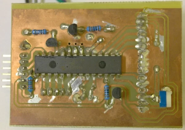
The next step is to make the controller PCB. Here you have two options, you can either etch a PCB based on my PCB layout, or you can solder the components on a prefboard and make all the connections by yourself according to my schematic. Personally, I suggest the first option because the end result is going to be much better and the circuit will be much more reliable.
Because this is not a tutorial on how to etch PCBs I’m not going to get into detail on how to do the etching, there are already many tutorials on the web if you want to know.
Now, about the soldering part, there are some things you need to be careful.
First of all, note that the microcontroller and the 3 transistors must be soldered on the copper side of the PCB. But on the other hand, the pin headers and the crystal must be soldered on the non copper side. As for the resistors, the capacitors and the trimmer pot you can solder them either side you want.
Apart from the components, you also need to solder directly from the PSU on the PCB the 5V Stand By signal (purple cable), the Power Good signal (gray cable), the Power On signal (green cable) and the Ground signal (black cable). Be sure to use heat shrink tubing where possible.
Note that if you have an ICSP programmer like PICKit you don’t have to worry about programming the microcontroller yet. You can solder it and program it directly on the PCB through the ICSP header. However, if you don’t have an ICSP programmer you need to make sure to program the microcontroller before soldering it. Jump to Step 5 if you want to read about programming the microcontroller.
Attachments
- pic_atx_psu.brdDownload
- pic_atx_psu.schDownload
- pic_atx_psu.pdfDownload
- pic_atx_psu_mirrored.pdfDownload
Step 3: Assembling the PSU
Now that you have all the parts you need, it’s time to prepare the chassis of the PSU to put the LCD screen, the switches and the banana connectors.
First, you will have to make six holes big enough to fit each banana connector. Then, you need one big square hole to fit the LCD screen plus 4 small holes for the screws of the spacers. Lastly you need 3 small square holes for the momentary switches.
The next thing you need to do is to mount the banana connectors to the chassis. Be very careful any metal part of connectors not to be in contact the chassis because it will make a short circuit. After that you need to screw the spacers on the 4 holes around the big square hole you made for the LCD display.
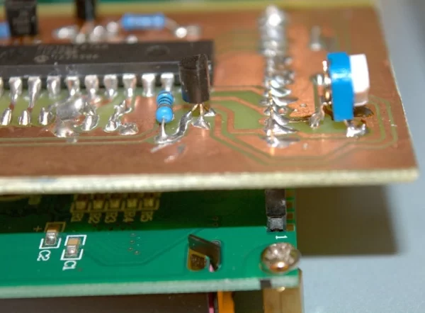
Next step is to screw the LCD on the top of the spacers. Make sure the copper pads of the mount holes make good contact with the spacers and the screws because you want the ground of the LCD to be connected to the chassis. Some LCD modules also have one or more jumpers that need to close in order to connect the ground of the PCB to the chassis. On my LCD these jumpers where called J1 and J2. You need to put a bit of solder to close them.
After screwing the display into place you can connect the female pin header of the controller PCB to the male pin header of the LCD.
Now you need to place the momentary switches in each of the three square holes. To easily connect them with the controller PCB you can use three half female jumper wires. Solder one side of each half with one side of every switch and connect the other side of the jumper to the pin header on the controller PCB. The other side of each switch needs to go to the ground. Because the chassis of the PSU is already grounded if you want you can just solder it directly on the chassis. Keep in mind though that the chassis of the PSU has a very large thermal capacity so try to use a bigger tip with your soldering iron than the one you normally use and set it to a higher temperature. Finally, put some hot glue to protect the switches from vibrations.
Next, you need to attach the current sensors to each rail of the PSU. To do that you can remove the plastic around the two input pins and directly solder the one of the two pins on each banana connector (except of ground). Be very careful any module not to touch the chassis.
On the other input of each sensor module solder the cables of each rail of the power supply. The yellow is 12V, the red 5V, the blue -12V, the white -5V and the orange 3.3V. For maximum current capacity on each rail tie all same color cables together before you solder them on each sensor input, but preserve one 5V cable because you are going to use it to power the sensor modules and one more 5V or one 12V (depending on your power supply) because you are going to use it to connect the dummy load resistor. You also need to preserve two ground wires.
Now you just have to connect all the GND pins of the sensors with the one of the two ground cables you preserved and all the VCC pins with one 5V cable you preserved. For this purpose you can use ten half female jumper wires. Finally, connect the five OUT pins of the sensors with the pin header on the controller board using five female to female jumper cables.
Lastly if your PSU has any exposed metal areas that might come in contact with the controller board put same electrical tape to insulate them. For example in my PSU there where two large heat sinks that where almost touching the controller board. So for safety I put same electrical tape on top of them.
Step 4: Adding the Dummy Load
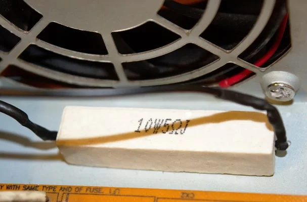
Because the ATX PSUs are switch mode power supplies they require a minimum load in order to be stable. The load needs to be on the rail that the PSU has the maximum current capacity. That is typically the 5V rail on older PSUs and 12V on newer PSUs. To figure out were you should connect the dummy load resistor simply check were your power supply can supply the most current. For example my PSU can supply a maximum of 35A on the 5V rail and 16A on the 12V rail, so I connected the dummy load between 5V and ground. Most PSUs require a minimum of around 5W of load in order to be stable. So you need either a 5Ω resistor on 5V or an 22Ω resistor on 12V. The resistor needs to be rated at least 10W otherwise it might catch fire.
To connect the resistor solder one of its leads with the 5V or 12V cable you preserved (depending on you PSU) and the other lead with the ground cable you preserved. Don’t forget to use heat shrink tubing to prevent any shorts. To secure the resistor in place you can use some hot glue. I recommend putting the resistor as close to the fan as possible because it’s going to release a lot of heat.
Step 5: Programming and Calibration
When you are finished with the hardware part of the PSU it’s time to program and calibrate the controller board. To do that you are going to need an ICSP programmer. If you don’t have an ICSP programmer you could program the microcontroller before you solder it on the PCB but you will not be able to do any calibration.
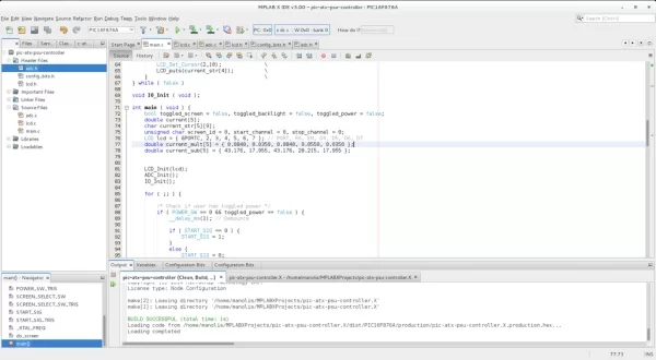
To compile the code you need to have installed the MPLAB X IDE and the XC8 compiler, so make sure that you have both installed.
The full MPLAB X project with the source code can be found on Github. If you have Git installed on your system you can simply clone the repository on a local directory by running the flowing command.
git clone https://github.com/magkopian/pic-atx-psu-controller.X.git
If you don’t have Git installed you can download the latest release from the releases page. If you do it that way make sure to rename the project folder from pic-atx-psu-controller.X-x.x.x to pic-atx-psu-controller.X otherwise MPLAB X might give you an error when you try to compile the code.
To program the microcontroller using a programmer supported by MPLAB X such as PICKit 3 it’s very straightforward. Just connect your programmer with the ICSP header of the controller board, open the project using the MPLAB X IDE and then hit the “Make and Program Device” button. If your programmer does not fit inside the PSU you can connect it to the ICSP header using jumper wires. In case of a PICKit you just need five female to male jumper wires. Also, make sure the PSU has power before you try to program the microcontroller.
If you don’t have a programmer supported by MPLAB X IDE you need to only compile the code without programming the microcontroller to generated a HEX file. When you have the HEX file you can use the software that comes with your specific programmer to burn it to the microcontroller. To only compile the code without programming the microcontroller just hit the “Build Project” button. After that you will find the HEX file inside the project folder in the subdirectory dist/PIC16F876A/production/.
To calibrate the PSU you simply have to edit the values on the lines 75 and 76 inside the file main.c before you compile the code. If have only used the 5A modules a good starting point is to use 0.0350 as a multiplier and 17.955 as subtractor for all five sensors and compare the current measurements of the PSU to a multimeter. Keep adjusting the multiplier and subtractor and reprogram the microcontroller until you are satisfied with the measurements.
Source: Convert an ATX PSU Into a Bench PSU That Measures Current
About The Author
Muhammad Bilal
I am a highly skilled and motivated individual with a Master's degree in Computer Science. I have extensive experience in technical writing and a deep understanding of SEO practices.