
In this instructable I am going to show you how to build a Star with 64 LEDs. The Star operates by itself but the operation mode can be changed when connecting it to a computer via a serial (RS232) interface. After reconfiguring the Star via the computer, the Star will use the new operating mode as the new default.
The Star can of course be used during the Christmas period but it can also be used as a night light on a children’s bedroom since the stars has various modes that could help kids to go to sleep. This has not been proven by research :-).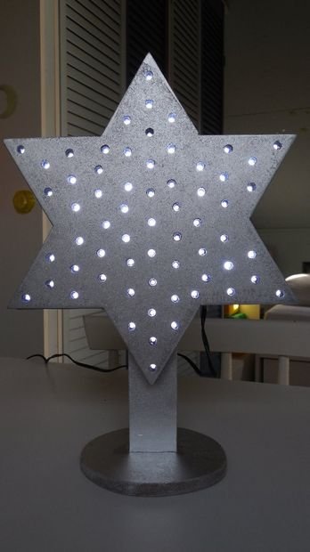
To summarize, the star has the following main features:
- Control 64 LEDs individually with different brightness. The brightness can be set from 0 (off) to 15 (maximum). The Star uses an initial pattern when switched on but this pattern can be changed via the serial interface.
- Blinking mode, which is changing the brightness of the individual LEDs to create a blinking Star effect. A variant to the blinking mode is the sparkling mode. See the attached document in one of the next steps for more info on this.
- Test mode. This mode can be used to see if you build the star correctly.
- Flashing Star mode. In this mode you can program your own sequence of LEDs that the Star will then use to switch these LEDs on and off one after another with the given brightness.
- Random mode. The random mode can be used in various ways, e.g. for generating random Star patterns but also to create a random flashing Star pattern.
- Auto off mode. When activated, the LEDs are slowly turned off. This is a nice feature when you use it in a children’s bedroom (‘You have to sleep before the star is off :-)”.
My hobby is in electronics and software development and I am not an expert in mechanical constructions so feel free to create your own variants. The housing is built using 8 mm and 4 mm MDF, glued with wood glue. The electronics is based on a PIC microcontroller.
See the following video in which the various functions are demonstrated. Since the LEDs are multiplexed, it may sometimes be a bit difficult to see the exact changes in operation but I think that in most cases it is visible.
Step 1: Step 1: Star ingredients
So you need to have the following to create this Star:
- 8 mm MDF panel
- 4 mm MDF panel
- 1 strip of wood of 4 mm by 9 mm
- Wood glue
- 1 bread board for assembling the electronics
- Paint. I used Silver colored paint
- 64 * White LEDs (in fact I only mounted 63 LEDs)
- 1 * Yellow LED
- 1 * Fuse of 200 mA/Slow + fuse holder
- 1 * 9 pin Female D-Connector
- 1 * PIC microcontroller 16F1825 + 14 pin IC socket
- 1 * MAX232 RS233 driver IC + 16 pin IC socket
- 2 * 74HC595 shift registers + 16 pin IC sockets
- 1 * LM2940 Low drop 5 Volt regulator
- 1 * 1N5819 Shottky diode
- 1 * 33 k resistor
- 5 * 1 uF/25 Volt electrolytic capacitor
- 1 * 47 uF/16 Volt electrolytic capacitor
- 1 * 470 uF/16 Volt electrolytic capacitor
- 5 * 100 nF ceramic capacitor
- 8 * BC557 transistor
- 8 * BC639 transistor
- 8 * 2k resistor
- 8 * 1k resistor
- 9 * 220 Ohm resistor
- 1 * 16 pin female header (I used 17 pins but that is not mandatory)
- 1 * 16 pin male header (same remark about the 17 pins)
- 1 * DC adapter, 6 Volt/200 mA
Step 2: Step 2: Building the Electronics
See the attached schematic diagrams that show the following parts:
- Power supply with PIC microcontroller and RS232 interface
- Shift registers
- LED output drivers
- LEDs in an 8 by 8 matrix
The first three parts are assembled on a bread board. The LEDs are mounted on a front panel as described in the next step.
LEDs and bread board are connected using a female header on the bread board and a male header for the connection with the LEDs on the front panel.
With the attached Intel Hex file you can program the PIC microcontroller.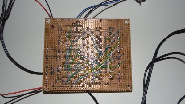
Step 3: Step 3: Creating the front panel with the LEDs
The front panel is made with 8 mm MDF and contains the holes for all 5 mm LEDs. Before I mounted the LEDs, I first sprayed the front panel with Silver paint. Note that only 63 LEDs were mounted because otherwise it would not give a symmetrical layout.
The LEDs are connected in a matrix of 8 by 8 according to the schematic diagram given in the previous step. I used Kynar wire to connect the wires. It is recommended to use different wire colors as much as possible. The wires are finally connected to the 16 pin Male header. The order of the wires is not important. It is only important to remember which wires are the scan lines and which wires are the return lines. Note that the Male header has to be mounted after the wires have gone to the back panel, see the next step.
For the front panel to be connected to the back panel you need a small trip of wood that is glued around the edges of the front panel as shown in the photo.
For more detail: Computer Controlled Star
About The Author
Ibrar Ayyub
I am an experienced technical writer holding a Master's degree in computer science from BZU Multan, Pakistan University. With a background spanning various industries, particularly in home automation and engineering, I have honed my skills in crafting clear and concise content. Proficient in leveraging infographics and diagrams, I strive to simplify complex concepts for readers. My strength lies in thorough research and presenting information in a structured and logical format.
Follow Us:LinkedinTwitter