
This project aims to implement a protocol-compatible iClicker substitute to provide students with a cheaper alternative to in-class polling while allowing the university to keep its existing investment.
High Level Design
Rationale
Our motivation from this project comes from our personal experience. iClickers are inconvenient and expensive yet required for at least one class at some point during our college career. Students forget their clickers at home regularly and despite performing such a basic function, they can cost upwards of $50. Since both of us are interested in security and reverse engineering we decided to create a platform that allows students to use a device they always have on them, their phone, as an iClicker.
Functionality/Logical Structure
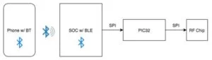
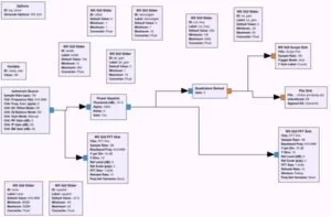
In terms of functionality, we would like our device to perform identically to a standard iClicker remote. This would allow the university to continue using the existing iClicker base stations that it has already heavily invested in, while providing a much cheaper alternative for students. As an additional advantage, this will allow teachers to continue using the iClicker software and Blackboard integration that they are comfortable with instead of having to interface with a new service. The device itself will act as a proxy and essentially provide an IP to RF bridge. Clicker responses from users will be sent via WiFi to a phone that is connected via Bluetooth to our device. The phone will send requests over the Bluetooth connection, causing the PIC32 on the device to generate appropriate RF transmissions that appear to come from distinct iClickers. The high-level architectural diagram is shown below in Figure 1.
Hardware
The hardware requirements of our project are relatively simple as all we need is an RF module and microcontroller for basic functionality. The addition of Bluetooth was optional but we felt it would make our platform simpler-to-use and more functional. We considered using the PIC as a USB host but decided against it as it wasn’t as seamless as a completely wireless system.
RF
Initially, we had ordered the Hope Electronics RFM12B module as it was extremely cheap but as we later found out, it is not capable of interfacing with the iClicker base station. The RFM12B supports a maximum bit rate of just 115.2 kbps but the iClicker operates at 152.34 kbps. The slightly more expensive RFM22B does support the bitrate required by the iClicker system, so we used this module instead.
Bluetooth
To interface with the phone, we decided to use a Cypress Bluetooth Low Energy Pioneer Kit as we already one on hand and its reasonable cost did not exceed our design constraints. Although the PSoC 4 is a complete system-on-chip and can just as easily communicate with the RF chip directly, due to the project requirements, it instead acts as a simple BLE to SPI bridge and relays all data to the PIC32 which is responsible for further processing. The chip supports many advanced bluetooth configuration parameters and the GUI driven development platform makes it extremely easy to work with.
Setup
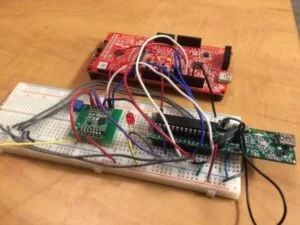
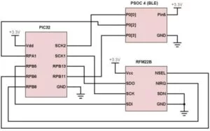
Our complete hardware set up is shown below in Figure 2. We borrowed an iClicker base station from the school to test with so that we did not disrupt any classes.
Software
The software development was by far the most challenging part of this project. With many different components, it took us a while to get everything working together.
Reverse Engineering
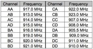
In order to make our device compatible with the existing iClicker base stations, we had to emulate the functionality of the standard iClicker remotes. This involved reverse engineering the protocol used to communicate between the remote and base station. Initial investigation into the FCC EMC test for the iClicker remote (using the FCC ID T24-RLR13) found a handy table, shown in Figure 3, that listed the specific frequencies used by the remote, depending on the selected channel.
Using a software-defined radio platform like the relatively cheap RTL-SDR, we were able to record and demodulate the transmissions from the standard remote. Tuning the RTL-SDR to the default frequency AA at 917 MHz while clicking buttons on the remote shows two individual peaks in the FFT, shown below in Figure 4, suggesting FSK modulation.
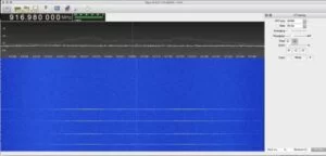
Other attempts at reverse engineering the iClicker protocol confirmed that it is indeed 2-FSK modulation, based on a XE1203F RF transceiver in the original iClicker hardware. Inspecting the two frequencies in the waterfall, we found that the frequency deviation is around ~250 kHz (which is confirmed to be 240 kHZ in the FCC EMC test). Using gnuradio-companion, we created a flow graph to demodulate the 2-FSK signal, shown below in Figure 5.
Armed with the demodulated data, we began reverse engineering the encoding protocol. The demodulated data did seem to be noisy so we ended up also using a Teensy 3.1 connected to a RFM22 module with a custom version of the Radiohead library to help debug the signals as we could easily record and replay the data.
iClicker Analysis
To start reverse engineering, we decided to send different responses from our own iClicker and analyze the data for any patterns. We received data for all different buttons (A, B, C, D, and E) and began to look at the data:
| Button | Data |
|---|---|
| A | 176 173 20 27 14 42 48 160 1 176 173 20 27 14 42 49 84 76 176 173 20 27 14 42 56 52 39 |
| B | 176 173 20 27 14 170 180 69 48 176 173 20 27 14 170 187 112 0 176 173 20 27 14 170 180 0 72 |
| C | 176 173 20 27 15 171 188 128 62 176 173 20 27 15 171 181 211 208 176 173 20 27 15 171 186 106 204 |
| D | 176 173 20 27 15 203 192 207 65 176 173 20 27 15 203 198 24 34 176 173 20 27 15 203 192 114 65 |
| E | 176 173 20 27 15 75 79 8 176 173 20 27 15 75 72 228 176 173 20 27 15 75 72 90 |
Immediately we saw that each button would send three redundant messages to ensure the base stations receives the vote. We also realized the last three bytes were constantly changing so we guessed that they did not matter (which turned out to be false). Focusing on the difference between different buttons, the 5th and 6th byte seemed to change depending on the specific button. We expanded those two bytes to binary to see if we could find which bits might specify the button:
| Button | Data [5,6] |
|---|---|
| A | 00001110 00101010 |
| B | 00001110 10101010 |
| C | 00001111 10101011 |
| D | 00001111 11001011 |
| E | 00001111 01001011 |
We saw a total of 5 bits changing between button presses. We checked out some resources that had dealt with iClicker hacking previously to see if we could confirm our suspicions. Based on some research by Arko, we confirmed that the middle 4 bits that were changing mapped to the button clicked.
- A = 0x1
- B = 0x5
- C = 0xD
- D = 0xE
- E = 0xA
Next we had to figure out how the clicker’s unique ID was encoded into the message. We started by expanding an entire button message into binary and expanding the ID into binary to see if we could see any similarities. At a first glance there were parts of the ID in the message, but nothing clear enough to work off of. We did a little more research online and found a paper regarding iClicker security by Derek Gourlay, Yik Lam Sit, Yuan Sunarto and Tim Wang. In this paper we found that the onboard eeprom held the clicker’s ID. In fact, it hold only the first 3 bytes of the ID because the last byte is just the XOR of the first three bytes. We then decided to try to reprogram our clicker’s ID and see how the packet changes to see if we could figure out the encoding that way. In order to do this we went off off Arko’s research. We soldered on a ISP header to the iClicker’s PCB to manipulate the microcontroller (Atmega8A). As well, after some testing and reading more of Akro’s research we soldered wires to the Atmega’s Vcc and GND line directly because the power management circuitry in the clicker would turn off the system every time we attempted to program the chip. After this, we were able to read out the EEPROM and we were happy to see our iClicker’s ID’s first three bytes: (0x0D51B3)
We then played around with changing the ID slightly and analyzing the packets to determine any corresponding changes. However we were unable to decode much of the message based on the ID. Luckily, while reading more of Gourlay, Sit, Sunarto, and Wang’s paper we found that the clicker’s ID is obfuscated when a packet is sent. The four of them had gone through the disassembled firmware on the iClicker to calculate the obfuscation. We decided to do the same to see if we could recreate the same results.
We found another fellow hacker, Andrew Rossignol, who had also worked on some iClicker hacking. His git repo had a disassembly of the iclicker firmware which we used. Once we had the assembly, we knew there was some shifting of sorts going on, so we searched for the assembly logical right shift command “lsr”. There were only 11 matches. Six of them were in a section with four load operations which led us to think this is where they stored the obfuscated ID to memory. Right above that code there were three function calls followed by storing the return value (r30) into r16, r17, and r18 respectively. These registers were then used in the following code containing the shifts so we thought r16-18 contained the actual ID of the clicker.
We manually went through the assembly, calculating exactly what was stored to memory and found the majority lining up with the other paper. However, there were significant differences that led us to question whether we were correct or not. After some more research, we found a small piece of code written by Ryan Hitchman which calculated an obfuscated iClicker address in python. We compared our findings to his code and it matched up. We also realized the four bits that represented the button pressed were in the last half of the 4th obfuscated byte. The full obfuscation is in Figure 7.
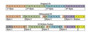
Now knowing how the ID was encoded into the message we did some more testing to figure out the rest of the encoding. One thing we realized was that the obfuscated message was not aligned within the packet. After the sync messages, the packet was a 0b101, followed by the 4 bytes of obfuscated ID. This left 5 bits of the last byte unknown, but we felt since the rest of the messages were offset there was probably a whole byte that was unknown. We double checked with our previous readings to confirm this because the three most significant bits of the 5th byte were the same for all three packets sent.
We spent many hours going through the assembly to see if we could see where this last byte was calculated. We checked memory addresses near the obfuscated ID, function calls when port bit corresponding to a button was cleared or set, and other various methods. We came up with nothing and proceeded to do some research online. Sadly this time we came up empty handed. We spent another three or so hours trying to figure it out by manually trying capturing packet data for many different IDs to see if we could find a pattern. Again, we could not. Finally, we decided we would just try all 256 possible combinations for that unknown byte and hope for the best. Remarkably, this technique worked and we were able to recreate the iClicker messages by sending 256 different packets for a single button press. While this is not the most optimal thing to do, it gets the job done.
iOS/Web App
In order to interface with the hardware, we decided we wanted to use bluetooth to create a completely wireless system that could be deployed in a classroom permanently. As we had previous iOS development experience, we decided to make the client app for an iPhone. The CoreBluetooth framework is used to connect to our custom peripheral and interface with the PSoC 4. The app, shown below in Figure 8, waits until it detects the Bluetooth chip and then connects.

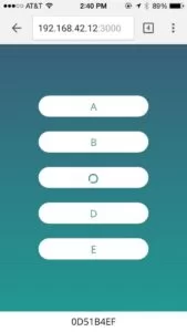
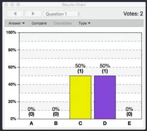
To allow users to vote without a physical clicker, we created a web app in Node.js that allows users to input their clicker ID and vote with the same clicker interface they are used to. Using Socket.IO, the iOS app is capable of receiving button presses from the web app from any number of users and relays them via Bluetooth to the PIC. The web app, shown in Figure 9, provides feedback of the vote status, allowing users to be confident that their vote was sent.
Bluetooth
Bluetooth Low Energy defines a standard method for communication between two devices based on a concept of services and characteristics. Making use of GATT, or the Generic Attribute Profile, the PSoC 4 was configured with a custom Bluetooth service and characteristic that is used for SPI data. The PSoC 4 acts as GATT Server, advertising its available services, and the phone acts as a GATT Client. Since we only need unidirectional traffic, we define a Write Without Response characteristic per the Bluetooth specifications. This allows us to send Bluetooth messages from the iOS device to the PSoC 4 without waiting for an acknowledgement.
PIC32/RFM22B
The PIC32 receives the clicker ID and vote information via SPI, computes the encoded RF packet and transmits it via SPI to the RFM22B chip. Configuring the RFM22B to meet the requirements of the iClicker base proved to be challenging. The RFM22B is designed to be a complete end-to-end system and normaly operates in packet handling mode. In this mode, the hardware automatically prepends packet headers and calculates CRCs to all transmitted packets, something that the iClicker does not do. For our use case, we attempted to use the RF chip in a raw packet transfer mode that would let us transmit and receive raw data without this preprocessing. Based on our earlier analysis, we knew most of the configuration parameters that are used but ended up referring to prior work by Mike Ossmann on Github to figure out some of the more obscure settings that the iClicker uses. The RF chip was configured with the following parameters:
- FIFO mode
- 917 MHz
- 152.34 kbps bit rate
- 255khz deviation
- FSK
- 8 bit preamble
- 3 Sync Word (0xB0, 0xB0, 0xB0)
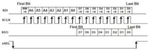
All communication with the RFM22B is performed via 16 bit SPI transfers. The first bit of the transfer is used to denote a read or write operation (0 for read, 1 for write). The next seven bits are the register address. At this point, a read will begin to clock out data on the MISO pin for the following 8 cycles, as shown in Figure 10. For a write, the next 8 bits would be the desired value.
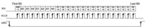
In addition, the FIFO registers support burst read and write operations that are used to read data during a receive operation or provide data to send during a transmit. The timing diagram is shown below in Figure 11.
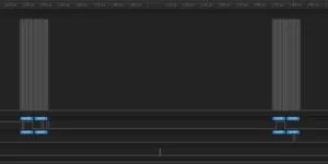
During this process, we found it extremely difficult to debug the RF code as it was very hard to tell what was happening. Using a Saleae Logic 4 to analyze the SPI communication, we found that the RF chip would never detect the last bit in the transfer, as shown in Figure 12. This turned out to be incorrect SPI configuration on the PIC that caused the data to be clocked out on the incorrect edge and was fixed by adding the SPI_OPEN_CKE_REV parameter to be set. Looking closely at the bus capture, it is clear that the last bit of data is clocked out on the rising edge of the CLK signal, which does not meet the setup time requirement of the RFM22B module.
Once SPI communication was working, we had to configure the chip correctly. Hope RF provides an Excel spreadsheet that can be used to calculate register values for the 128 8-bit configuration registers based on the desired parameters. We used this to calculate the register values needed for communication with the iClicker base and they can be found in our source code for the PIC.
Results
Our project was able to replicate an iClicker’s functionality with just a few small user experience differences. The iClicker base station detects multiple clicker IDs and correctly registers votes while maintaining compatibility with existing physical clickers as shown in Figure 13.
Speed of Execution
Due to network latency, there is approximately a 1-2 second delay between a user pressing a button and the vote being registered. We feel this is a justifiable tradeoff for the reduced cost to students as the system is still completely functional even if it is a bit slow.
Efficiency/Usability
In terms of usability, our current design only allows one vote to be transmitted at any given time to ensure that the base receives the vote. However, if there were multiple requests from different users at the same time, the later one would be dropped. This problem is easily addressable if we had more time as we can queue up votes to be sent.
In terms of implementation details, our project was very inefficient due to the encoding scheme. This is because we had to send 256 messages for a single button click, with all different combinations for one of the bytes as were were not able to calculate the value deterministically. The nice part is that this implementation detail is abstracted from the user which allows them to use the product without realizing this hack. Given more time and further analysis of the firmware, we believe we can break the clicker obfuscation and replace this component.
Safety
Our design was laid out on a breadboard for ease of development and consists of low voltage components that are completely harmless if somebody was to come in contact with it. If this product was commercialized, we would build an enclosure that can be safely tucked away in a corner. The RF signal generated by the transmitter is far below all legal regulations and is completely safe to be around.
Interference
If there are other devices operating on the same frequency as we are, we are confident our design will still work because in a typical classroom setting, there are hundreds of iClickers casting votes simultaneously that all get processed.
Conclusion
Overall, our project was a success. We were able to replicate the iclicker protocol and allow users to cast votes as any ID using their phone.
Potential Changes
There are few changes we would make if we had more to time to invest in this project. The obvious one is to spend some more time going through the firmware to determine how the last byte in the packet is calculated. We would do this by using a simulator to run the assembly and step through the code to see exactly what is being transmitted and how it is calculated. As we touched on earlier, we could also queue up votes being sent to the RF chip to allow multiple votes to be combined into single packets, improving the performance. Another improvement would be to process the acknowledgement packet the base station sends out. Currently we just send the packet and expect it to get there, but it would be better to confirm the base received the packet in the same way that the iClicker remote currently does. Finally, we could replace using the PIC32 and just use the PSoC 4 and radio module to simplify the design. We could also then design a small PCB and housing for the radio module and PSoC 4 to make it more professional.
Ethics/Legal Considerations
Throughout our project, we consulted the IEEE Code of Ethics to make sure we followed these important principles. Naturally, when reverse engineering an existing commercial system, the question of ethics always comes to light. We feel that while we are replicating a protocol, we are not breaking any copyright laws. The lack of patents on the device indicate that there is no trade secrets at stake and since the device has been legally obtained, we are well within the legal boundaries to reverse engineer the system. According to Sec. 103(f) of the DMCA, reverse-engineering for the purposes of interoperability is permitted. In addition, the lack of preventative methods like enabling the AVR protection bit suggest that security was not a primary concern. We have given credit to every person/team or paper that we used in designing our project and hope they critique our work just as we have done to theirs. Similarly we have mentioned any flaws that our current design has so that anyone who decides to use or improve on what we did will know exactly what we did. Lastly, we designed this product with safety in mind to make sure nobody will get hurt while using it.
Standards/FCC
Although, the RFM22B does not include FCC certification (as it drives up the unit cost), it was developed to follow all FCC regulations to allow end users to eventually request their own FCC approval. The RF chip operates on the 915MHz band which falls within one of the unlicensed ISM bands for Region 2 use (which includes North America). As we are transmitting at just 4dB, we fall well below the allowed threshold and comply with all FCC regulations. This design would not be legal in different regions but since the iClicker system does not operate outside of the 915MHz band anyway, our platform is useless in all other regions.
Data Security
The iClicker system advertises a secure voting platform to keep votes and personally identifiable data independent. In order to keep our system secure, we would eventually connect our web application to the university’s single sign-on service to prevent students from using a clicker ID that was not their own for academic honesty purposes. Since the entire service is online, the student has very limited ability to attempt anything malicious.
Schematic
Source: Clicker Clone
About The Author
Muhammad Bilal
I am a highly skilled and motivated individual with a Master's degree in Computer Science. I have extensive experience in technical writing and a deep understanding of SEO practices.