Hello all and welcome to my second Christmas related project.
Have you ever received a really boring Christmas card? Have you ever sat there and thought to yourself “If only there were a little video game on this card that I could play…” Well ponder no more because that card is here!
This instructable will show you how to make your very own retro video game Christmas card which can be made for less than $10. All you need is some time, some soldering know how and roughly $10 in your wallet.
There are essentially two main parts to building this project.
1. Soldering all the parts to the vero board (experimenters board)
2. Making the card itself (this is where you can get creative)
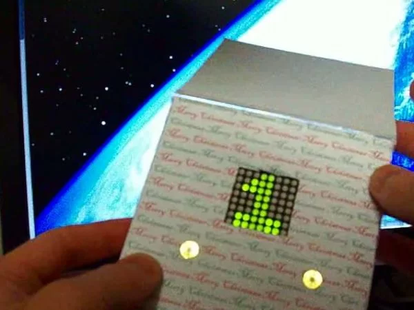
The game is titled “Santas Scramble” and is played within 64 pixels on an 8×8 LED matrix display. You play santa (a red dot) who is frantically flying around the world in order to get all of the presents delivered to the children in time for Christmas, the only problem is that he has flown into a dangerous maze. Your job is to steer santa up and down the screen in order to avoid the oncoming obsticles. Be careful, the further you get through the game, the faster it gets. If you crash then it is – GAME OVER –
There are two different designs below and I must apologise for my lack of arts and crafts ability. My strong point is the electronics side of things…
Anyway – lets get started shall we!
Step 1: Gathering together the required parts.
As stated in the introduction, there are essentially two main parts to this instructable.
1. Building the electronic circuit
2. Constructing the card
[box color=”#985D00″ bg=”#FFF8CB” font=”verdana” fontsize=”14 ” radius=”20 ” border=”#985D12″ float=”right” head=”Major Components in Project” headbg=”#FFEB70″ headcolor=”#985D00″]
Here is what you will need for the electronic circuit:
– 1 x pic 16f648a microcontroller
– 1 x 7442 (1 of 10 decoder IC)
– 2 x cr2032 batteries
– 2 x cr2032 battery holders
– 1 x 32 hole by 23 hole piece of veroboard / strip board
– 2 x push buttons
– 1 x 8×8 bi-colour LED matrix display
– 9 x 150 ohm resistors 1/4 watt
– 2 x 10k ohm resistors 1/4 watt
– length of enamel wire (the really thin wire with a coating of enamel for insulation)
– shorter length of single core wire
– Soldering iron
– Solder
– scalpel (or sharp knife)
– solder wick (optional but handy if you make a soldering error)
– Flux (optional but helps with soldering)
– pic microcontroller programmer
here is what you will need for the card:
– paper (all sorts of colours to make it more interesting)
– thin cardboard
– thick corrugated cardboard (the cardboard that packing boxes are made from)
– glue stick
– double sided tape
– sticky tape
– scalpel (or sharp knife)
– scissors
– what ever else you can think of to make a nice looking card[/box]
Handy Hints:
– Pay a visit to sure electronics webstore where you can buy a lot of 10 Led matrix displays for around $8.60 this makes them 86c each!
– ebay is a great place to buy electronic components. Make sure you do a worldwide search since postage is normally quite cheap for lightweight components.
– Head on over to microchip.com and sign up to their online store. Then you can buy parts directly from them. For example here in Australia it would cost me $10 for a 16f648a microcontroller. But if I buy them from microchip they are just over $1.
– You can also request free samples from microchip. I think you can get about 6 free samples a month. This has been very handy for me in experimenting with different chips.
Step 2: Program the microcontroller
At this stage, you will want to program your microcontroller with the santas scramble game hex file. There are many different programmers out there so I will not be able to explain the exact process.
You can download the hex file from the bottom of this page.
Simply open the hex file in your programming software and burn it to the microcontroller. Then you are ready to commence construction!
Step 3: Cut the board to size.
The veroboard (strip board) will need to be cut to 32 holes by 23 holes.
Please see the photo below for reference.
Note that the tracks are aligned vertically.
Step 4: Soldering all the components onto the board
I like to solder in everything in one big hit. Then from there we can cut the necessary tracks and solder our enamel wire to form a complete circuit. (which will be covered in the following two steps)
But for now, lets just solder in the components. Have a look at the photo’s below for the location of each component. One item to note is the 8×8 LED matrix. You must insert it the correct way otherwise it won’t work. See the third photo for a close up.
Also you should note that both the microcontroller and the 7442 IC are mounted such that pin 1 is to the bottom left.
You can see both the top (component side) and the reverse (solder side) of the board.
Step 5: Cutting the veroboard tracks
As it is, we have shorted out all of our IC’s legs from top to bottom as well as the resistors, buttons and LED matrix. We need to cut a whole heap of tracks in order to make sure that we are not shorting out any of the components.
Please refer to the photo’s below for a look at where to cut the tracks. The first photo shows where the tracks have been cut by red ovals. The second photo is exactly the same just with the ovals removed for clarity.
Step 6: Study the Schematic.
You can download the schematic below. Have a look at it since you will need to match the circuit you are building, to this schematic.
It is very likely that some of the components that you will be using will not match my components exactly (E.G the led matrix and push buttons) so it is important that you study the schematic diagram and as long as you wire together yours accordingly, you will be just fine!
Here is a direct link to the original full size schematic:
http://www.instructables.com/files/orig/F9A/MK4K/G3KY0ONB/F9AMK4KG3KY0ONB.png
I have also included the pinouts for the pic16f648a microcontroller and the 7442 decoder IC.
Power is provided by two CR2032 batteries connected in series (I.E the -ve of one battery is connected to the +ve of the second thus providing you with 6volts to power the circuit. This 6volts connects to the GND and VCC connections indicated in the schematic provided.
Step 7: Completing the circuit with enamel wire
Enamel coated wire is fantastic for veroboard projects.
The enamel coated wire comes in many guages, but I prefer to use .25mm thick enamel wire. This can be bought in little reels at most electronic stores or online.
Even though the wire looks like it is not coated (insulated) it actually is – with a very fine varnish so it is fine for the wires to touch each other (I.E. they wont short each other out.) Before you can solder these wires on though – you must first strip the ends. The easiest way to do this is to put a blob of solder on your soldering iron and then place the end of the wire into the molten blob, this will melt off the tip of the enamel wire which will give you a ‘stripped’ end ready to be soldered to the board.
The first photo shows strands of wire ready to be ‘stripped’ the second photo shows those same wires with the ends removed of enamel. The third photo shows the completed board. With all connections made.
you will also notice that I have used thicker wire with the green insulation. These are the power connections.
Here is a description of the five green wires:
– 1st battery +ve to 2nd battery -ve
– 1st battery -ve to microcontroller GND and 7442 GND
– 2nd battery +ve to microcontroller VCC and 7442 VCC
Step 8: Circuit testing
Once your circuit is built you will obviously want to test it.
Pressing either of the buttons will turn the screen on and the game will start to play. If you then press the down button, you player should move down. If you press the up button, your player should move up.
If you hit a wall the game should stop and present you with the level number that you made it to.
If you complete the game, then you should be presented with a smiley face.
Pressing either of the buttons on any end game screen should take you back to the start of the game.
If you dont press any buttons for approx 30 seconds, the game should go into standby mode and the screen will turn off.
* PLEASE NOTE * upon further testing, standby mode draws quite a bit of current and as such your batteries will die in a matter of days EVEN WHEN NOt BEING PLAYED. I highly recommend that you add an ON / OFF switch to your circuit to fix this problem.
For more detail: Christmas card with inbuilt retro video game for under $10
About The Author
Ibrar Ayyub
I am an experienced technical writer holding a Master's degree in computer science from BZU Multan, Pakistan University. With a background spanning various industries, particularly in home automation and engineering, I have honed my skills in crafting clear and concise content. Proficient in leveraging infographics and diagrams, I strive to simplify complex concepts for readers. My strength lies in thorough research and presenting information in a structured and logical format.
Follow Us:LinkedinTwitter