
This project is specially designed to measure surface mount capacitors in the range 1p to 920n and electrolytics in the range 1u to 100u.
The biggest problem with surface mount capacitors . . . they are not identified!
And you cannot determine their value by the size of the component.
This makes it very difficult.
Unless you know the value when taking it off a reel, they can get mixed up and fitting a 22n in place of a 47p will create a lot of problems.
This project is a low-cost piece of test equipment especially designed to test these devices in the range 1p to about 100u . . . capacitors 1u and larger are identified on their body with values such as 105 for 1un, 106 for 10u and 107 for 100u.
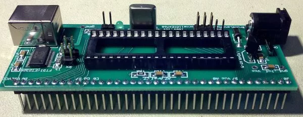
Surface-mount capacitors are also fiddly to hold and test at the same time, so we have designed a set of tapered contacts where the capacitor is held with tweezers and moved down the contacts until it is gripped by the contacts. Then a reading can be made.
Simply hold the button ON and the display will produce a reading.
The CIRCUIT
The circuit diagram is very simple but a lot of “design consideration” has gone into the 4 components used to detect the value of a capacitor. The biggest problem is the range of capacitance we want to measure. The circuit detects capacitance values from 1p to 100u. This is a range of 100,000,000:1 or 108:1
The normal way to measure the value of a capacitor is to charge it via a resistor and see how long it takes to charge to 66% of the charging voltage. This length of time is called a TIME CONSTANT and applies to a capacitor when a particular “charging resistor” is used.
For instance, if we have a 1p capacitor and 100k resistor, the time constant will be:
(100,000 ohms x 1Farad) / 1,000,000,000,000 = 0.1microseconds.
This means a 1p capacitor will charge in 0.1 microseconds when a 100k resistor is used to charge it.
We are using a PIC12F629 microcontroller and each instruction-cycle takes 1 microsecond. This means we can only “look at” the charge on the capacitor every microsecond and by this time it will be already charged – as it only takes 0.1 of a microsecond.
In fact the fastest-rate we can look at the charging of a capacitor is every 3-5 microseconds due to 3 instructions needed to create a “look” loop and this means the smallest capacitance we can detect is 50p and increments in amounts of 50p.
However there is one other feature built into the PIC micro that operates at up to 10MHz. It is called the COMPARATOR MODULE, but to make it easier to understand how it works, we will call it an OP AMP.
An Op-Amp has a NON-Inverting input (+) and an Inverting Input(-) and an output.
We have already discussed the OP-AMP in another article on Talking Electronics website, however the essential points to note are these.
The “+” input of the op amp can be supplied from an internal reference voltage and we have selected this voltage to be 60% (3v) of the supply voltage.
Since this voltage is a reference voltage, it must be fixed and that is why we have used a voltage regulator to supply an accurate 5v for the supply-rail.
When 3v is supplied to the “+” input of the op amp, the output is HIGH when the “-” input is at any voltage below 3v.
As soon as the “-” input rises a few millivolts above 3v, the output instantly goes LOW.
When the “-” input goes a few millivolts below 3v, the output goes HIGH again.
This means the “-‘ input only has to change a few millivolts and the output changes from HIGH to LOW.
The “-” may only need to be 1mV above and 1mV below 3v for the output to change. We don’t know the exact value but it does not matter. We just need to remember this characteristic.
Now we need to create a circuit that will charge a capacitor via a resistor, then discharge the capacitor to create an oscillator. By measuring the frequency of the oscillator we can determine the value of the capacitor.
If we place a capacitor on the inverting input with a resistor to the output of the op amp, we will create an oscillator. But the capacitor will only have to charge and discharge a few millivolts for the circuit to oscillate and this will produce a very high frequency oscillator. We cannot deal with a high frequency oscillator so we must improve the circuit.
By adding a diode across the charging resistor we will almost fully discharge the capacitor each time the output goes low and this will increase the charging time.
We have also added a 1k resistor so the charge on a large capacitor does not damage the output of the op amp when it goes low and this will also gives us a known amount of discharge.
For more detail: Capacitance Meter MkII using PIC12F629
About The Author
Ibrar Ayyub
I am an experienced technical writer holding a Master's degree in computer science from BZU Multan, Pakistan University. With a background spanning various industries, particularly in home automation and engineering, I have honed my skills in crafting clear and concise content. Proficient in leveraging infographics and diagrams, I strive to simplify complex concepts for readers. My strength lies in thorough research and presenting information in a structured and logical format.
Follow Us:LinkedinTwitter