Usea C-52 EVB for simple robot experiments. Build a simple two wheels robotwith L293D H-Bridge driver and IR sensors. Write a C program controls robottracked with black tape. Fun with Ving-Peaw Competition 2543, course layout,day-by-day changed rule and scoring also included!
Introduction
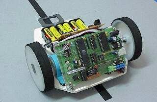
One of my student has made a disgracefulrobot that used two stepper motors and with a simple IR sensor. Yes, abovepicture is what I’m talking. Without battery carrying, a little bit torqueof the stepper and misalignment of driving shaft, makes it crawling notwalking, but first demo, showed quite impressive to me. He said he wrotea couple of program lines using C, his robot can track the black tape.I feel delighted his intention and endeavor. I thought, ” he borrowed meDS5000, expensive one, a soft uController with internal bootloader, whyshouldn’t try with our learning board C-52 Evaluation Board instead”. Anotherone, told me the same day “I found the L293 Push/Pull Four Channel Driverat Ban-Moah, it costs 1.5 US$ “. I’ve been searching this chip for a year.The MiniBoard,a Motorola 68HC11 Robot Controller board designed by FredG. Martin, also uses this driver. The day after, I then decidedto prepare the page describing how to use C-52 EVB as a robot controllerboard. I asked my student for competition, build yourselves robot thatcan track the black tape. Prize for the winner is 100 US$, with a bit conditionthat the winner must pay for a big party at Soi Jinda’s Somtum (PapayaSalad) shop. And one of the competitor is me. I thought the rule shouldbe conceived roughly by students and technically by me. The picture onthat day will put here soon.
C-52 EVB resources
Beforehand, let look at availableresources of C-52 EVB for robot experiments.
DC Motor Driver
Basic circuit of using L293 formsan H-Bridge Driver is shown in Figure 1. As shown for such inductive loadas DC motor, external diodes for suppressing back EMF must be connected.The MiniBoard uses L293D instead, the L293D has internal diodes, howeverproviding a bit less driving capacity, i.e., 600mA @4.5V-36V. From thetruth table, we see that direction of the motor can control by pin C andD. VINH enable/disable power to the motor, thus for speed regulation, wethen use this pin for PWM signaling. See details, L293.pdfdata sheet.
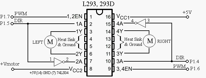
A circuit connecting C-52 P1 to L293 driver chip is shown in Figure2. As shown Enable pin 1 connected to P1.0 is for PWM signaling. We useadditional inverter at pin7 and pin 15 to provide proper logic for easydirectional control. Please note that pin 4,5,12,13 are tied to groundand if heat sinking needed, one method is to make a large area of PCB orsoldering it with a metal sheet, say.
My latest design put additional inverter forPWM signal at pin 1 and pin 9 to prevent full power delivering to DC motorswhen resetting the 89C52(i.e., all bits of P1 is logic high). Check thelogic of PWM pins for another microcontrollers.
Line Tracking Sensor (I have to KUK)
Since there’s no ADC for 89C52 chip, each competitor may build theirown Line Tracking Sensor, some may use LM339 QUAD comparator with IR transmitterand receiver, some may use LDR as described inLineFollower Robot . With an external comparator, it may not necessaryto have ADC, but with LDR, we need external ADC. ” Having additional ADCfor 89C52 would be better”, I thought. How can we provide ADC for 89C52with a cheap method? I chose PIC16C711 with 4-channel ADC, and 7-pin inputport. Interfacing to 89C52 is done with simple PISO protocol by using RB0for SCLK and RA4 for SDA. The code for such purpose was written in C, hereis the source file, C52ADC.C and the HEXcode, C52ADC.HEX. After some initialization,the 711 chip wait for trigger read signal at pin RB0, i.e., high-to-lowtransition, then it responses by sending 40-bit through RA4(SDA) with low-to-hightransition. 40-bit data stream begins with LSB of ADC0 to MSB of PORT B.Example of program fro testing ADC is ADC.Cand the hex file is ADC.HEX.
For more detail: C-52EVBRobot Controller
About The Author
Ibrar Ayyub
I am an experienced technical writer holding a Master's degree in computer science from BZU Multan, Pakistan University. With a background spanning various industries, particularly in home automation and engineering, I have honed my skills in crafting clear and concise content. Proficient in leveraging infographics and diagrams, I strive to simplify complex concepts for readers. My strength lies in thorough research and presenting information in a structured and logical format.
Follow Us:LinkedinTwitter