I apologise for the tardiness of this article; for the next little while, I will probably have to scale them back to once every two weeks or so. The reason is that I am proof reading the “Galley Proofs” of my new book, “PC PhD”. This book discusses the PC’s hardware and how to develop interfaces (along with the required software) for it. I’ll be putting more information about it on my web page as the August release date comes up.
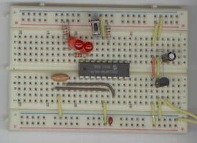
In my last article, I presented you with a simple circuit as a first application. I want to continue with this circuit to demonstrate five different methods of software based “debouncing”.
A typical switch connection used in a digital application is:
In this circuit, the Microcontroller input pin is held high until the button is pressed (the switch is “closed”). When the switch is closed, then a direct path to ground is made with the Microcontroller Pin being “pulled” to Ground.
“Bouncing” is the term used to describe what happens when the switch is closed or opened. Instead of a single, square edge as you may expect, a switch change consists of many short spikes which are a result of the button’s contacts “bouncing” during the transition. This is shown in the diagram below:
These spikes can cause a microcontroller to detect many button pressing events. As is shown in the diagram above, when “Button Pressed”, the signal actually received by the microcontroller’s input pin looks like the series of “spikes” that I have shown. These spikes are characteristic to the button and are generally present for about 10 milliseconds.
In the diagram above, I have shown the Logic “High”, “Low” and “Threshold” levels. The “High” and “Low” values should be easy to understand, but I wanted to spend a moment on the “Threshold” level. This is the voltage level in which the microcontroller detects the difference between a “High” or a “Low” input. For TTL circuits, this value is generally about 1.4 Volts while for CMOS circuits (as are used in the PICMicro), the threshold is normally one half Vcc, or 2.4 to 2.6 Volts.
While 10 milliseconds is quite short for us humans, it is actually quite long for a digital circuit and the period between spikes is often enough for the application to respond to the request and set up to wait for another button press, which comes as another keystroke.
To the user, it will seem as if the Microcontroller is responding to multiple button presses for each individual one. From the Microcontroller’s perspective, this is exactly what is happening.
To prevent this rapid repeat of button press operations a “debounce” routine like the one shown in psuedo-code below is used to wait for the button transitions to stop for 20 msecs before acknowledging that a button has been pressed:
For more detail: Button Debouncing using PIC16F84 Microcontroller

