The Goals
Sometimes you need to check one circuit and test some of its nodes. Usually a tester in voltage mode is a good solution, but it has a pair of problems. First, it measures about zero both when the node is driven at zero volts and when the node is floating (not driven at all). Second, it gives the information on the tester display, so you need to take the view from the circuit to the tester to check the voltage.
The proposed circuit somewhat qualifies as a logic probe. It should give no indication when the node is not being driven and it should give a different indication when the node is driven at high or a low voltage.
A lot of logic probes are not self powered. They rely on the circuit supply to operate. In my case I would like the probe to be usable also a as a continuity tester. If we set ground in one point of the circuit and we probe another point, the continuity can be detected between both points because a low level will be driven even if the circuit is not powered at all.
The Circuit
The following figure shows the schematic of the circuit.
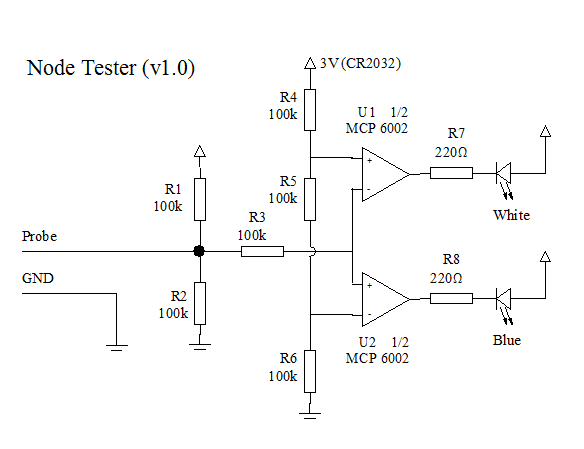 |
| Probe Schematic |
The circuit is powered with a 3V CR2032 battery. When the probe is not connected to anything, the probe voltage, as set with R1 and R2 will be 1.5V. As both Operational Amplifiers (MCP6002) have very low bias current (1pA), no voltage drops on R3 and 1.5V is also seen on the non inverting input of U2 and on the inverting input of U1.
Resistors R4, R5 and R6 define a voltage divider that sets 1V on the inverting input of U2 and 2V on the non inverting input of U1. With 1.5V on the probe, both operationals saturate at high level (3V) so both LEDs are OFF.
If we set the probe tip to a voltage below 1V (The trip point of U2), U2 will saturate at low level and the Blue LED will turn ON. In a similar way, if the probe tip voltage is set above 2V (The trip point of U1), U1 will saturate at low level and the White LED will turn ON. I know white is a strange color for high level. A red color will be better buy I had no red LEDs similar to the blue one at hand.
Operational Amplifiers are not the best suited components for this project. As they are used as compactors, a dual comparator could be better in this case. The choice of the MCP6002 dual opamp was only because I had them available.
For more detail: Building a simple circuit probe
About The Author
Ibrar Ayyub
I am an experienced technical writer holding a Master's degree in computer science from BZU Multan, Pakistan University. With a background spanning various industries, particularly in home automation and engineering, I have honed my skills in crafting clear and concise content. Proficient in leveraging infographics and diagrams, I strive to simplify complex concepts for readers. My strength lies in thorough research and presenting information in a structured and logical format.
Follow Us:LinkedinTwitter